Battery Energy Storage System (BESS): What Really Matters Before You Choose One
Table of Contents
- How solar battery energy storage systems work in conjunction with photovoltaic systems
- How commercial battery energy storage systems reduce energy costs
- How industrial battery energy storage systems manage peak loads and power supply risks
- What performance and safety criteria should be evaluated when selecting a C&I energy storage system
What Is a Battery Energy Storage System—and Why Is It More Than a Battery?
A battery energy storage system (BESS) is a comprehensive system for storing, converting, and dispatching electrical energy. It can store electricity from solar panels or the grid and then release it when electricity prices are high, solar generation is insufficient, demand rises, or the grid experiences an outage. A complete BESS consists not only of batteries but also includes a battery management system (BMS), power conversion system (PCS), energy management system (EMS), thermal management, electrical protection, fire suppression, and monitoring systems.
According to data from the International Energy Agency (IEA), global new battery storage capacity will reach 108 GW in 2025, representing an increase of approximately 40% compared to 2024; global installed battery storage capacity will be approximately 11 times that of 2021. This makes battery storage one of the fastest-growing power technologies today.
a. A BESS Is a System, Not Just a Battery
- The battery determines how much electricity can be stored
- The PCS (Power Conversion System) determines the power at which charging and discharging can occur
- The EMS (Energy Management System) determines when to charge and when to discharge: It formulates strategies based on PV generation, load, electricity rates, and operational objectives.
- The BMS (Battery Management System) ensures the battery operates within safe limits: It monitors voltage, current, temperature, SOC, and faults.
- Thermal management and fire suppression systems control operational risks: Manage cell temperature differentials, overheating, gas buildup, and the risk of thermal runaway propagation.
b. Battery, Battery System, BESS, and ESS: What Is the Difference?
| Concept | Core Function | Does Not Include or May Not Include |
|---|---|---|
| Battery | Stores energy in electrochemical form and outputs direct current. | PCS, EMS and AC grid-connection control. |
| Battery System | A battery-side system consisting of cells, modules, battery packs, BMS and related protection. | May not include PCS or a project-level EMS. |
| BESS | Integrates the battery system, PCS, EMS, thermal management, fire protection, safety features, metering and monitoring into a complete energy storage system. | Whether transformers, switchgear and on-site installation are included depends on the scope of supply. |
| ESS | A general term for energy storage systems. | Not limited to batteries. It also includes pumped-storage hydro, flywheels, compressed-air energy storage and thermal energy storage. |
For manufacturers planning to build or expand battery production capacity, choosing the right battery PACK line is also an important consideration. ChinTiyan shares 10 questions before you buying a battery PACK line.
c. What Does a BESS Actually Do?
A BESS is not a power generation system. It stores existing electricity and releases it when it is needed most. For your project, it primarily performs three functions: shifting electricity, controlling power, and converting this flexibility into electricity cost savings, supply reliability, or grid services.
1. Shift Energy to the Hours You Need It
2. Control Power, Not Just Energy
- 200 kW determines the power the PCS must provide
- 100 kWh is the amount of electricity that needs to be released during the peak period
3. Turn Flexibility Into Measurable Value
| Project Objective | How the BESS Operates | Key Considerations |
|---|---|---|
| Increase PV Self-Consumption | Stores excess PV energy during the day and discharges it when the load requires it. | PV surplus curve, nighttime load and feed-in tariff. |
| Peak Shaving | Discharges when the site load exceeds a defined power threshold. | Peak power, peak duration and demand-based billing method. |
| Load Shifting | Charges during off-peak periods and discharges during peak-price periods. | Peak-to-off-peak price difference, system efficiency and battery cycling costs. |
| Backup Power | Supplies stored energy to designated critical loads during a grid outage. | Grid-forming capability, transfer equipment, critical-load power and required backup duration. |
| Reduce Solar Curtailment | Stores solar energy that would otherwise be curtailed or restricted from export. | Curtailment periods, available storage capacity and grid-connection rules. |
| VPP or Grid Services | Adjusts charge or discharge power in response to external dispatch commands. | Market access, communication protocols, response speed and available SOC reserve. |
How Does a Battery Energy Storage System Work?
The Three Stages of BESS Operation
1. Charge: Electricity Enters the Battery
2. Store: The BMS Keeps the Battery Within Safe Limits
3. Discharge: Stored Energy Returns to the Load or Grid
- The EMS calculates the target discharge power.
- The BMS confirms that the battery status permits discharge.
- The battery outputs direct current (DC).
- The PCS converts the DC to alternating current (AC) that meets the required specifications.
- The electrical energy enters the AC busbar to supply the load or be fed into the grid.
How Energy Flows Through a Solar-Plus-Storage System
AC-Coupled System
- PV Power Supply: PV → PV Inverter → AC Bus → Loads or Grid
- Battery Charging: AC Bus → PCS → Battery
- Battery Discharge: Battery → PCS → AC Bus → Loads or Grid
The PV inverter and energy storage PCS operate independently, making this configuration suitable for adding energy storage to existing PV projects.
DC-Coupled System
- PV Charging: PV → DC/DC or DC Bus → Battery
- PV Power Supply: PV → Hybrid Inverter/PCS → Loads or Grid
- Battery Discharge: Battery → Hybrid Inverter/PCS → Loads or Grid
How the System Is Controlled
- EMS: Determines when to charge or discharge and how much power to deliver.
- BMS: Monitors the battery’s status and authorizes, limits, or stops charging and discharging.
- PCS: Performs bidirectional conversion between DC and AC power.
A Simple Day in a Solar Battery Energy Storage System
Suppose you operate a factory with a rooftop PV system and a BESS:
| Time | PV Power | Factory Load | BESS Action | Grid Power |
|---|---|---|---|---|
| 12:00 | 800 kW | 500 kW | Charging 250 kW | Remaining 50 kW exported to the grid or limited by the control system. |
| 19:00 | 100 kW | 700 kW | Discharging 200 kW | Grid supplying the remaining 400 kW. |
At noon, the PV system first meets the factory’s load. The remaining power is used to charge the battery. In the evening, PV output drops. The BESS discharges the electricity stored during the day, reducing the amount of high-cost electricity the factory purchases from the grid.
Can a BESS Use Solar and Grid Power at the Same Time?
Yes. Photovoltaic systems, the utility grid, loads, and battery storage systems can all be connected to the same project simultaneously, but the specific energy flow must be coordinated by the EMS.
Q1: Can a BESS Charge from Solar?
Yes. Storing excess solar power is one of the most common operating modes for a solar battery energy storage system.
Q2: Can a BESS Charge from the Grid?
Generally, yes, but this depends on the PCS functionality, EMS strategy, electricity pricing mechanisms, and local grid connection regulations.
Q3: Can Solar and the Grid Be Connected at the Same Time?
Yes. The EMS coordinates the power from each component based on PV output, load demand, battery SOC, and control objectives.
Q4: Can a Battery Charge and Discharge at the Same Time?
A single battery system is typically in either a net charging or net discharging state; it does not perform opposite operations simultaneously through the same interface.
Q5: Can a BESS Export Power to the Grid?
Technically, yes, but the project must comply with grid connection agreements, export power limits, and market access requirements.
Q6. Can a BESS Provide Backup Power During an Outage?
Yes, but the BESS must be equipped with a PCS that supports backup power or island operation, along with switching devices and circuits for critical loads.
Learn more: Explore how a hybrid inverter coordinates solar PV, batteries, and the grid.
What Are the Core Components of a BESS?
A battery energy storage system (BESS) typically consists of batteries, a BMS, a PCS, an EMS, thermal management, fire protection, electrical protection, and monitoring and communication systems.
The Eight Core BESS Components
| Component | Primary Function | What You Should Check |
|---|---|---|
| Battery Cells, Modules and Racks | Store electrical energy. | Battery chemistry, rated and usable capacity, C-rate, DOD, cycle-test conditions, EOL definition and warranty. |
| BMS | Monitors and protects the battery. | Cell-level monitoring, SOC and SOH accuracy, cell balancing, protection thresholds, alarm records and communication compatibility. |
| PCS | Performs bidirectional AC/DC power conversion. | Continuous and peak power, DC voltage range, efficiency curve, THD, power-factor range and grid-tied or off-grid capability. |
| EMS | Develops and executes system-level charging and discharging strategies. | Time-of-use strategies, peak shaving, PV forecasting, VPP interface, local control and remote dispatch. |
| Thermal Management | Controls temperature and cell-to-cell temperature differences. | Air or liquid cooling, operating-temperature range, temperature uniformity, auxiliary power consumption and maintenance requirements. |
| Fire Protection | Detects, isolates and controls fire risks. | Smoke and gas detection, tiered alarms, fire-suppression media, smoke exhaust, system isolation and interlock logic. |
| Switchgear and Protection | Provides electrical isolation and fault protection. | Circuit breakers, fuses, contactors, surge-protection devices, emergency stop, grounding and maintenance isolation. |
| Metering, Communication and Cloud | Collects, transmits and displays operational data. | Data granularity, sampling frequency, RS485, CAN, Ethernet, API access, data ownership and remote-update capability. |
BMS, PCS and EMS: Three Roles You Should Never Confuse
① BMS Defines the Battery Safety Boundary
The BMS in a battery energy storage system is responsible for monitoring the voltage, current, temperature, SOC, and fault status of individual cells and battery modules. Upon detecting an anomaly, it can limit power output, trigger an alarm, or disconnect the battery circuit.
The core mission of the BMS is safety, not revenue optimization. You should focus on checking protection thresholds, SOC/SOH estimation accuracy, cell balancing capabilities, and whether fault records are traceable.
② PCS Converts Electricity Between DC and AC
- During charging: The PCS converts the AC power supplied by the PV inverter or the grid into DC power and feeds it into the battery.
- During discharging: The PCS converts the DC power output from the battery into AC power to supply on-site loads or the grid.
③ EMS Turns Hardware Into an Operating Strategy
The EMS in a battery energy storage system integrates PV power, load, electricity prices, SOC, and grid connection constraints to calculate the charging and discharging power for each time slot. The EMS should support peak-valley arbitrage, peak shaving, PV self-consumption, demand response, and remote dispatch. It should include not only data dashboards but also automated control logic.
④ Safety Depends on the Entire System
The BMS cannot replace thermal management, fire protection, or electrical protection. Uncontrolled temperatures, sensor failures, contactor malfunctions, or communication interruptions can all compromise system safety.
For lithium-ion battery energy storage projects, you should also verify the applicable standards and scope of certification. For example:
- IEC 62619:2022 covers safety requirements and testing for lithium-ion batteries in industrial and stationary applications.
- IEC 63056:2020 further specifies safety requirements for lithium-ion batteries used in energy storage systems with a maximum voltage of 1,500 V DC.
⑤ What Does “All-in-One Energy Storage System” Mean?
A Real Specification Example: Sunways STA-HT 125/261
The Sunways STA-HT 125/261 is a liquid-cooled all-in-one energy storage system. It has a rated power of 125 kW and a rated capacity of 261 kWh, corresponding to a nominal discharge duration of approximately 2.1 hours:
261 kWh ÷ 125 kW ≈ 2.1 hours
The actual operating time must also account for SOC reserve, conversion losses, auxiliary power consumption, and temperature derating.
The product specifications also list LFP batteries, liquid cooling, aerosol fire suppression, IP55 protection, and RS485, CAN, and Ethernet communication. The cycle life is listed as 8,000 cycles, but the corresponding test conditions are 0.5P charging, 0.5P discharging, 100% DOD, and 70% EOL. When comparing BESS components, one should not focus solely on “8,000 cycles” or “261 kWh.” Test conditions, usable capacity, system power, and safety configurations must be considered together.
Where Does a BESS Create Real Value?
Match the Business Problem to the BESS Function
| Your Project Challenge | BESS Function | Typical Projects |
|---|---|---|
| Excess daytime solar generation and high evening electricity consumption. | Solar Self-Consumption | Factories, hotels, shopping malls and office buildings. |
| Short-term load peaks are increasing demand charges. | BESS Peak Shaving | Factories, warehouses and EV charging stations. |
| A significant difference exists between peak and off-peak electricity prices. | Load Shifting | Commercial buildings, industrial facilities and industrial parks. |
| The grid is unstable or power outages occur frequently. | Backup Power | Hospitals, data centers, production lines and weak-grid projects. |
| Diesel generator runtime and fuel costs are too high. | Diesel Reduction | Off-grid, microgrid and backup-power projects. |
| PV output is subject to export restrictions or solar curtailment. | Curtailment Reduction | Large rooftop PV systems and ground-mounted solar plants. |
| The project is eligible for demand response or flexibility markets. | VPP or Demand Response | Eligible European commercial and industrial energy projects. |
Three Ways a BESS Creates Project Value
a. Lower Electricity Costs
Commercial battery energy storage systems can charge during periods of excess PV generation or low electricity prices and discharge when load or electricity prices peak. A project generates actual returns only when the savings on electricity bills exceed conversion losses, battery degradation, auxiliary power consumption, and O&M costs.
- Peak shaving: Reduces peak power draw, lowering demand charges.
- Load shifting: Shifts the use of low-cost electricity to high-cost periods.
- Solar self-consumption: Stores excess solar power, reducing the need to purchase electricity from the grid.
b. Reduce Outage and Diesel Costs
c. Use More Solar and Provide Flexibility
Different Markets Need Different Priorities
| Target Market | Common Project Objectives | Data to Check | Issues Easily Overlooked |
|---|---|---|---|
| India | Peak shaving, solar self-consumption, and backup power during outages. | 15- or 30-minute load curves, demand charges, surplus PV energy, and outage records. | Electricity tariffs and grid-connection rules vary by state, distribution company, and customer category. |
| Pakistan, Bangladesh, and Sri Lanka | Backup power, diesel reduction, and solar-plus-storage. | Outage duration, critical-load power, diesel consumption, and on-site temperature. | Backup power, required duration, high-temperature derating, and cooling-system consumption must all be checked. |
| Italy, Spain, and Poland | PV self-consumption, time-of-use tariffs, EMS optimization, and VPP participation. | Electricity contracts, PV feed-in tariffs, dynamic or time-of-use prices, and market-access requirements. | Having an EMS and energy storage equipment does not automatically qualify a project to participate in a VPP or flexibility market. |
What Data Do You Need Before Choosing a BESS?
Before finalizing a battery energy storage solution, you can use the following formula to establish a preliminary value model:
Annual BESS Value ≈ Demand Savings + Energy Savings + Avoided Outage and Diesel Costs + Grid Service Revenue – Losses – Degradation – O&M
This formula represents the annual revenue generated by the BESS, minus the costs incurred from system operation. All project figures must be converted to the same currency and expressed on an annual basis.
For example, a project generates the following annually:
20,000 in demand charge savings + 15,000 in electricity cost savings + 10,000 in outage and diesel cost savings + 5,000 in grid service revenue – 3,000 in losses – 4,000 in degradation costs – 2,000 in O&M costs = 41,000 in annual net value. This represents only the annual operational value of the BESS and is not the return on investment (ROI). When calculating ROI or payback period, you must also factor in equipment, installation, financing, taxes, and replacement costs.
Not sure whether your project is better suited for peak shaving, solar self-consumption, or backup power? Start by analyzing your load curve, PV capacity, and local electricity rates.
Which BESS Design Is Right—Battery Type, Coupling and Cooling?
① LFP vs. NMC for Energy Storage
| Comparison | LFP | NMC |
|---|---|---|
| Cycling Performance | Generally better suited for frequent charging and discharging. | Depends on the specific cell design and operating window. |
| Thermal Stability | Generally better. | Requires stricter temperature control and safety design. |
| Energy Density | Relatively low. | Relatively high. |
| Raw Materials | Does not contain nickel or cobalt. | Typically contains nickel, manganese and cobalt. |
| Cost | Generally lower. | Generally higher. |
| Common Applications | Stationary energy storage and C&I BESS. | EVs and applications with strict space or weight constraints. |
LFP battery energy storage systems are better suited for stationary projects that prioritize cycle life, thermal stability, and cost. NMC batteries offer the advantage of higher energy density, making them more attractive when space or weight is strictly limited.
The International Energy Agency (IEA) reports that by 2025, LFP batteries accounted for over 90% of the global BESS market.
Source: IEA Global Battery Markets
② What About Other BESS Battery Types?
- Lead-acid: Lower initial cost and mature technology, but usable depth of discharge (DOD) and cycle life are typically lower than those of lithium-ion batteries.
- Flow battery: Power and capacity can be scaled relatively independently, making them suitable for long-duration energy storage, but they have a larger footprint and higher system complexity.
- Sodium-ion: Currently entering the commercialization phase, but energy density, supply chain, certification, and project experience still need to be verified on a product-by-product basis. The latest sodium-ion cells can achieve an energy density of approximately 175 Wh/kg, but the supply chain remains significantly smaller than that of lithium-ion batteries.
③ AC-Coupled vs. DC-Coupled BESS
| Comparison | AC-Coupled BESS | DC-Coupled BESS |
|---|---|---|
| Connection Method | PV and energy storage are connected separately to the AC bus. | PV and the battery are connected through a shared DC side. |
| Best Suited For | Adding energy storage to an existing PV system. | New solar-plus-storage projects. |
| Key Advantages | Easier retrofitting; the PV and storage systems remain relatively independent. | Fewer power-conversion steps when charging the battery from PV. |
| Key Limitations | PV energy may pass through more conversion stages before entering the battery. | A shared inverter may limit certain simultaneous operating conditions. |
| Expansion Method | PV and energy storage can usually be expanded relatively independently. | Expansion requires the DC voltage and inverter capacity to be checked again. |
④ Air Cooling vs Liquid Cooling
| Comparison | Air Cooling | Liquid Cooling |
|---|---|---|
| Temperature Control Method | Heat is dissipated through fans and air ducts. | Heat is transferred by coolant flowing through pipes and cold plates. |
| Structure | Relatively simple. | Higher system integration. |
| Temperature Uniformity | More susceptible to airflow design and environmental conditions. | Typically provides more uniform and precise temperature control. |
| Suitable Applications | Smaller-capacity systems, fewer cycles and relatively mild environments. | High-energy-density, frequently cycled or high-temperature applications. |
| Maintenance Focus | Fans, filters, dust accumulation and airflow paths. | Pumps, coolant, seals and leak detection. |
The goal of BESS thermal management is not only to prevent overheating but also to minimize temperature differences between cells. Excessive temperature differences can cause inconsistent cell aging rates, reducing the usable capacity of the battery cluster. An ideal thermal management system should maintain the battery pack within an appropriate and uniform temperature range.
The Sunways STA-HT125/261 features a liquid-cooled design that integrates a 125 kW PCS, a 261 kWh LFP battery, a BMS, an EMS, and a fire suppression system within a single cabinet. This design is suitable for C&I projects with stringent requirements for footprint, temperature control, and deployment speed.
Source: Sunways 2026 All-in-One Datasheet, pp. 58–59
⑤ All-in-One vs. Modular Energy Storage
| Design | Key Advantages | Key Limitations | Best Suited For |
|---|---|---|---|
| All-in-One Energy Storage System | Centralized components, compact footprint, and less on-site wiring and commissioning. | Less flexibility in equipment configuration; maintenance may depend more heavily on the supplier’s support system. | Standardized C&I projects and applications requiring rapid deployment. |
| Modular System | Greater flexibility in selecting the PCS, batteries, and other equipment; supports phased expansion. | More complex system design, communication integration, and on-site commissioning. | Large-scale projects, complex retrofits, and customized energy storage systems. |
A Simple Selection Rule
In actual projects, when retrofitting an existing PV system with energy storage, AC coupling is typically prioritized to minimize modifications to the original inverters and grid-connection system. For new PV-storage projects, DC coupling can be evaluated to optimize the energy path from the PV array to the battery.
For high-temperature markets such as India and Pakistan, liquid-cooled LFP systems should be prioritized if the project involves frequent daily charging and discharging cycles. However, for smaller-scale projects with limited cycle counts and budget constraints, air-cooled systems offer better value for money.
Sunways Solution Direction
For C&I energy storage system projects requiring an integrated liquid-cooling design, Sunways offers the following product options:
125/261kWh | LFP 314Ah Batteries
Rated Power:125 kW
Rated Energy:261 kWh
System Design:LFP, integrated liquid cooling, BMS/EMS integration
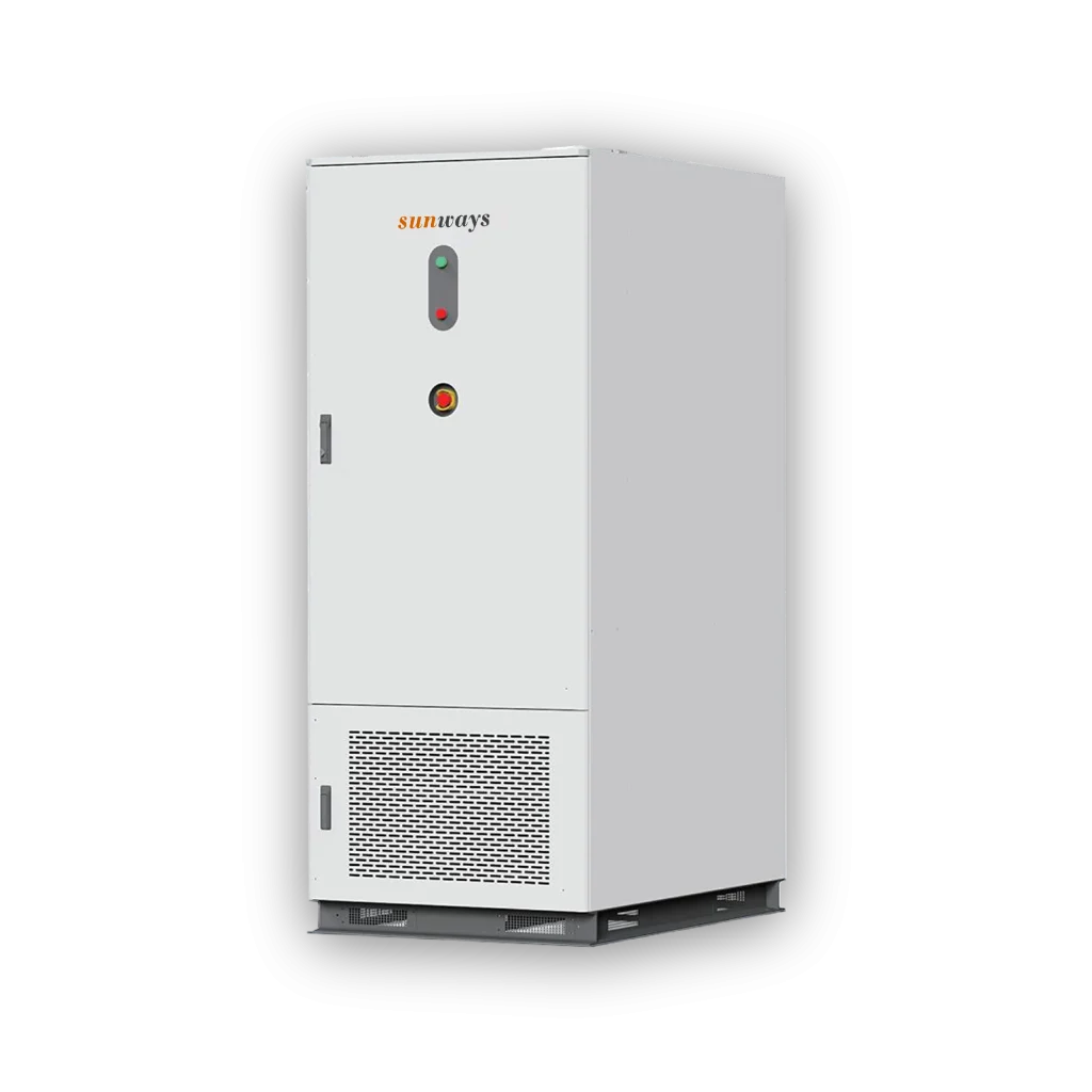
This product is suitable for C&I applications such as factories, commercial buildings, and industrial parks. However, the final model selection should not be based solely on rated capacity; it must also take into account load profiles, energy storage duration, grid connection voltage, backup power requirements, and on-site conditions.
Primary Commercial Destination
If you have your load profile, PV capacity, electricity tariff structure, and project location ready, you can view Sunways C&I solutions and submit your project requirements via the following page:
Not sure which BESS fits your project?
Share your load profile, PV capacity, electricity tariff, backup requirements, and site conditions. The Sunways team can help you identify a suitable power and energy configuration.
Start Your Project