Commercial Battery Storage: Is Your Business Ready to Invest?
Table of Contents
Is Commercial Battery Storage Worth It for Your Business?
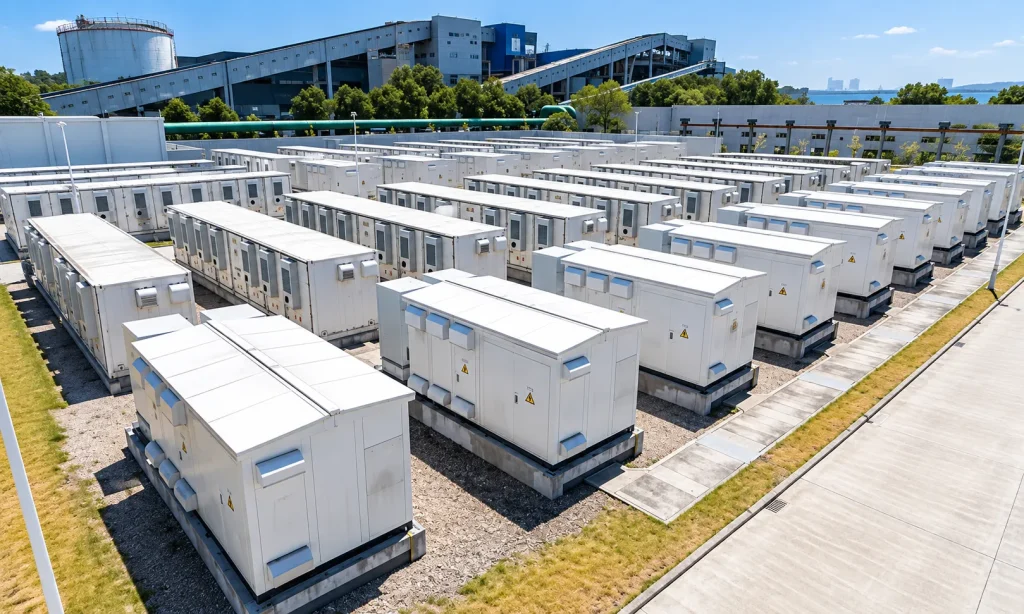
If power cuts would affect critical business operations, if you have surplus solar power during the day that can be saved for use at other times, or if there are electricity costs that could be reduced through energy storage, commercial and industrial battery storage is worth evaluating. Whether it is worth the investment depends on the tasks it can perform at your site and whether the realisable benefits or business continuity value can justify the total cost. First, clarify your requirements; then consider the size of the battery you need.
Commercial and industrial battery storage (also known as C&I battery storage) comprises batteries, inverters or power conversion systems (PCS), control systems and associated protection devices. It allows electricity to be stored for use when it is most needed, and—when configured with appropriate backup power functionality—can supply power to critical equipment during power cuts. You are procuring a system designed to fulfil specific tasks; therefore, your assessment should cover the equipment, installation, control systems, commissioning and subsequent operation and maintenance.
We recommend first establishing a verifiable objective. For example, which equipment should continue to operate during a power cut and for how long, or to what level the grid power draw should be reduced during specific billing periods. The more specific the objective, the easier it will be to judge whether the supplier’s configuration is reasonable, and to identify any equipment or engineering costs omitted from the quotation.
If you are currently unable to identify sufficient surplus photovoltaic power, clear opportunities for electricity cost optimisation, or critical backup power requirements that must be addressed, start by improving your electricity management. Energy storage should not be a project where you only begin to look for uses after the purchase has been made.
Backup, Peak Shaving or Solar Self-Consumption: What Does Your Site Actually Need?
If power cuts affect critical operations, first clarify the scope of backup power; if your bill includes peak charges that can be reduced, prioritise assessing peak shaving; if you have surplus electricity during the day but still need to purchase electricity afterwards, then assess solar self-consumption. A single system can serve multiple purposes, but you must first specify which objective must be prioritised; cost-saving measures must not be allowed to encroach upon committed backup power reserves.
Start with Your Site’s Operating Needs
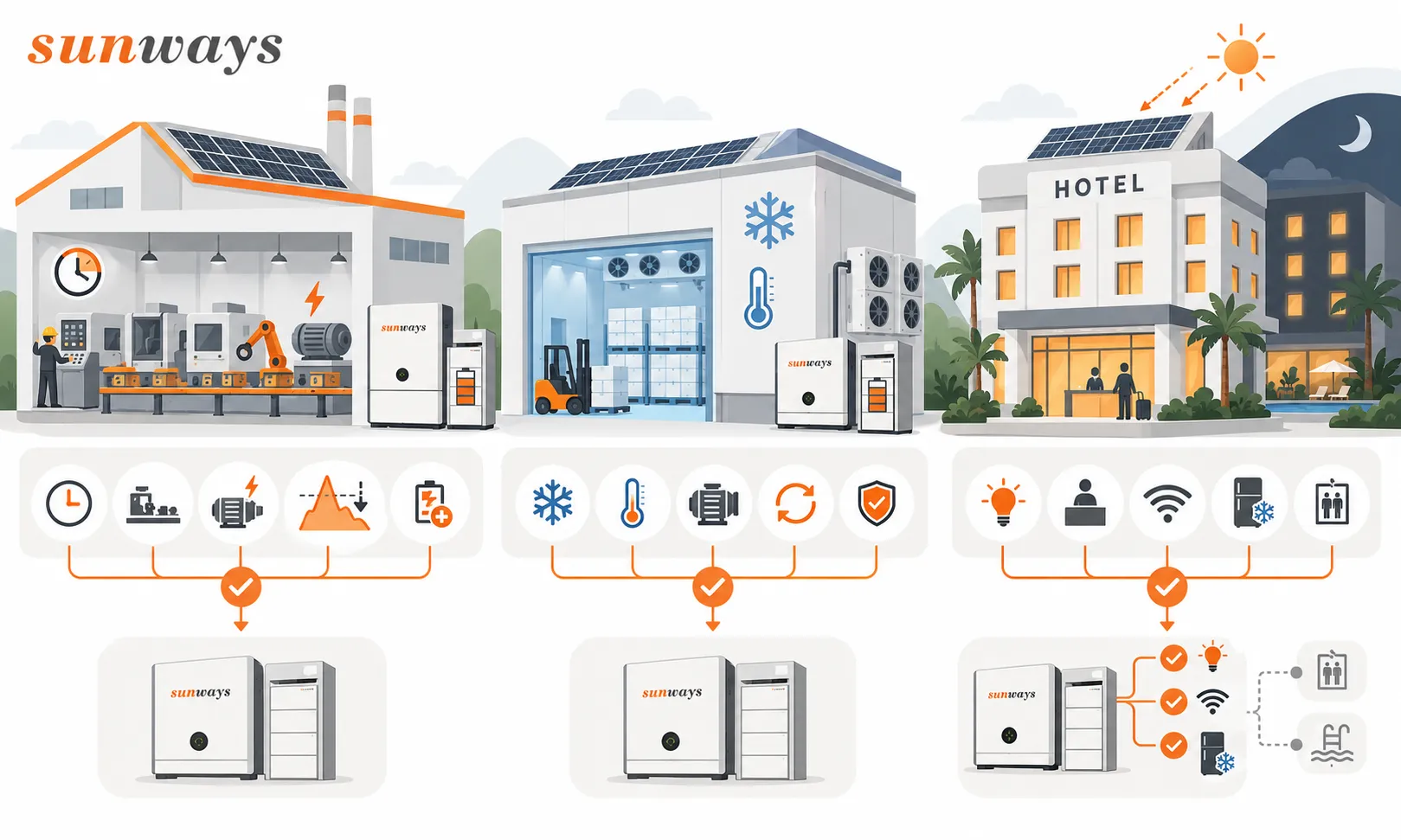
| Your scenario | What to check first | Priority assessment objectives | Actual selection criteria |
|---|---|---|---|
| Factory | Shifts, simultaneous equipment operation, motor start-up requirements, critical processes and billing methods | Assess peak shaving where relevant demand charges apply; prioritise backup power for processes that cannot be interrupted | First check whether operations can be staggered to avoid peak periods, then calculate how much energy storage is required to support the remaining peak demand. The scope of backup power should be specified for each individual process. |
| Cold stores / cold chain | Compressor start-up and operating cycles, permissible temperature range, acceptable downtime | Maintain essential refrigeration and temperature control functions | First verify start-up, switchover and restart conditions. Selecting a system based solely on the compressor’s normal operating power may result in sufficient power being available but the compressor failing to start. |
| Hotels | Surplus PV electricity during the day, evening loads, fluctuations in occupancy rates and essential services | Assess the use of surplus PV electricity for on-site consumption; configure backup power according to service requirements | First, determine the priorities for lighting, reception, networking, refrigeration and other services; do not assume that all air conditioning, kitchen equipment and lifts will be powered by batteries. |
The above are application scenarios, not Sunways customer case studies. For cold stores, operational staff should also confirm acceptable temperature fluctuations and downtime; for hotels, peak season full occupancy and off-season low occupancy rates may correspond to different electricity consumption profiles. Do not use a single ‘typical working day’ to represent the entire year.
Peak Shaving and Load Shifting Are Different
Peak shaving reduces peak grid draw, whilst load shifting alters the timing of electricity consumption. Whether peak shaving saves money depends on which charges in the contract are linked to peak demand or demand levels, and whether the energy storage system can reduce the corresponding billed amounts. For load shifting, one must compare electricity tariffs during high- and low-price periods, whilst factoring in losses and operating costs. Both functions are termed ‘cost savings’, but the basis for calculation differs.
Ask your supplier to first identify exactly which charges on your bill are likely to decrease. If charges are based on contracted capacity or other rules, reducing an instantaneous peak once may not necessarily alter your bill. For load shifting, one cannot simply multiply the price difference by the battery’s nominal capacity: the actual amount of electricity that can be charged and discharged each day, and on which days the system will operate, all require load data to support these calculations.
For self-consumption of PV power, the actual surplus electricity must also be considered. A large rooftop PV installation does not necessarily mean a significant amount of electricity will be stored in the battery; if most of the electricity generated during the day is already consumed, expanding the battery capacity may simply result in additional idle capacity. If the surplus electricity could originally have been sold, the value of the energy storage must be reduced by the foregone revenue from electricity sales.
Set the Priority, Then Check the Curves
Please ask the solution provider to align the load, PV generation and grid power inflow/outflow on the same timeline, marking peak electricity consumption, surplus electricity available for storage and key load periods. The curves should specify the metering location, date and sampling interval; avoid simply combining data from different meters or different months.
It is recommended to prepare data covering a continuous period of 12 months wherever possible, to verify shifts, weekends and seasonal variations; this is a data preparation recommendation, not a mandatory sampling standard for all projects. For new projects without historical records, estimates may initially be based on equipment operating schedules, but the assumptions must be clearly stated and verified after commissioning. Do not present predicted curves as on-site measurements.
Finally, establish a clear set of priorities for the project: prioritise critical business operations, reduce peak-load charges, or utilise surplus photovoltaic electricity. Include other uses as secondary benefits or operational constraints; this will provide a basis for determining future capacity and control strategies.
Adding Commercial Solar Battery Storage: Should You Choose AC or DC Coupling?
If you have existing PV equipment, prioritise assessing an AC-coupled retrofit for that equipment; if installing PV and storage together from scratch, compare DC-coupled hybrid inverter solutions at the earliest opportunity. Ultimately, the comparison should focus on the equipment, retrofit and operating costs required to complete the same task, rather than the efficiency of any single piece of equipment.
How Does Energy Flow?
AC coupling connects the PV system and the battery on the AC side, whilst DC coupling connects them on the DC side. The following is a typical simplified energy path, omitting distribution, metering and protection equipment; it does not represent a live-line wiring diagram.
| Architecture | PV power stored in battery | Battery supplies power to load |
|---|---|---|
| AC-coupled | PV modules → PV inverter (DC to AC) → AC busbar → battery inverter/PCS (AC to DC) → battery | Battery → battery inverter/PCS (DC to AC) → AC load |
| DC coupling: typical hybrid inverter configuration | PV modules → DC conversion stage of the hybrid inverter → battery | Battery → inverter stage of the hybrid inverter (DC to AC) → AC load |
When PV electricity is ‘stored first, then used’, a typical AC-coupled path involves three AC-DC conversions. DC coupling can usually reduce the number of conversions in this path, but there are still losses associated with DC conversion, the battery and auxiliary equipment. The figure ‘three’ here refers to the count of conversions in the aforementioned path; it is not the result of an efficiency test.
Do not directly infer that ‘one fewer conversion’ equates to ‘greater annual savings’. If your primary electricity consumption occurs during the day, most of the PV electricity may be supplied directly to AC loads without passing through the battery at all. What needs to be compared is the volume of electricity flowing through each path over the course of a year, as well as the efficiency of the equipment under the corresponding load conditions.
AC vs DC Coupling: What Changes for Your Business?
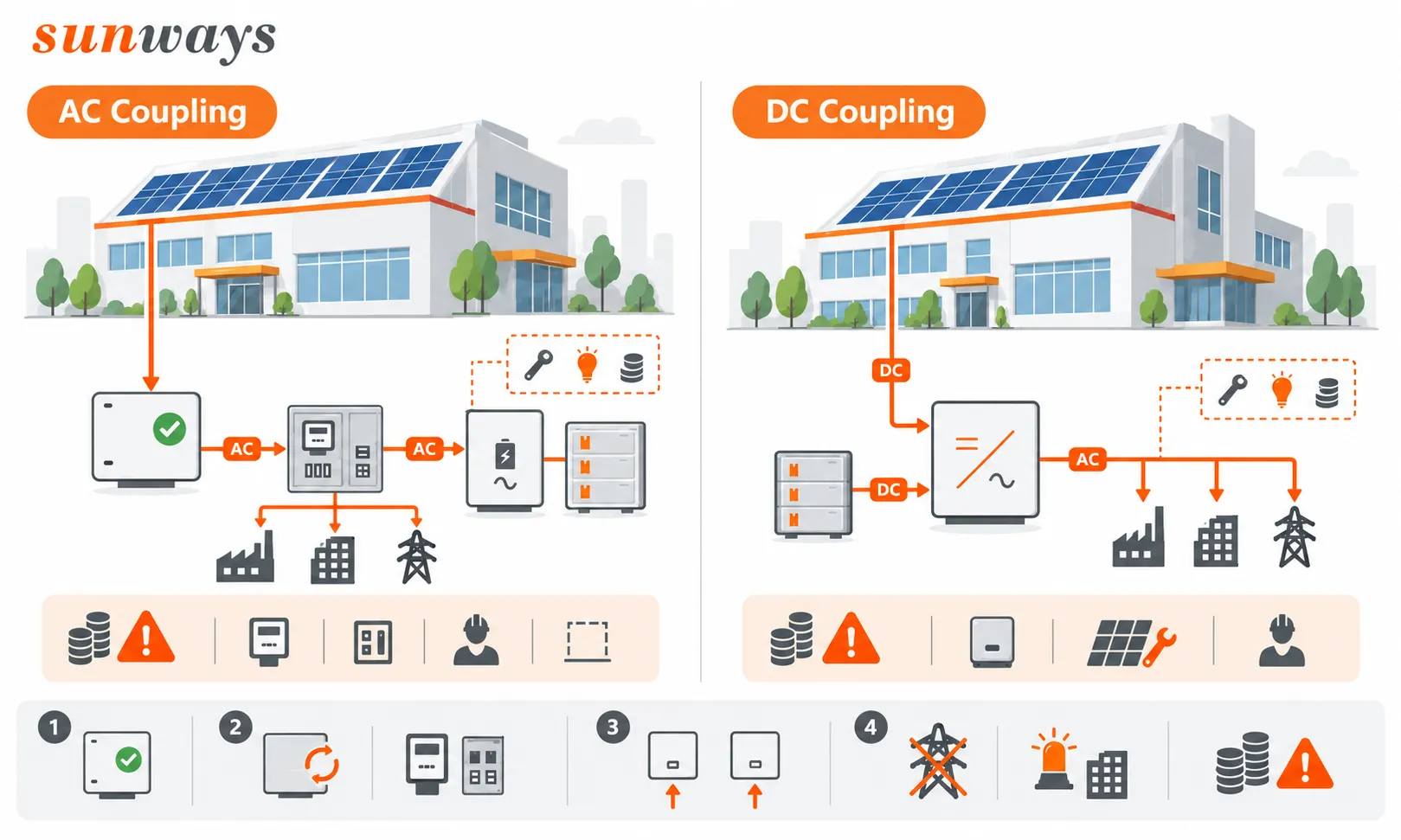
| Your concerns | AC coupling | DC coupling: Hybrid inverter solution |
|---|---|---|
| Can my existing PV equipment still be used? | Existing PV inverters can usually be retained; batteries and a PCS are added | Inverters may need to be replaced and PV wiring adjusted during retrofitting; new projects can be configured uniformly |
| What installation modifications are required? | AC power distribution, metering, control and installation space | Voltage and current matching between PV strings and batteries, as well as potential rewiring and construction-related downtime |
| What are the limitations of simultaneous power supply from PV and batteries? | Subject to the respective limitations of the PV inverter, PCS, power distribution and control systems | Typically shares the inverter output stage; the total output limit during simultaneous power supply must be verified |
| Will the system still operate after a power cut? | Appropriate off-grid power supply and isolation configurations are required; whether the existing PV system can continue to operate must be verified separately | A backup power function must be in place and correctly wired; one should not rely solely on the term ‘hybrid inverter’ |
| Which costs are commonly overlooked? | Power distribution modifications, metering and control integration between different devices | Costs associated with replacing existing equipment, rewiring and construction downtime |
Existing Solar: Check What You Can Keep
If your existing solar system is operating normally, first ask the installer to propose a plan for retaining the equipment. Check the existing wiring and distribution capacity, the location of the electricity meter, and how the solar panels and batteries are managed. If space on-site is limited or significant alterations to the distribution system are required, these factors should also be taken into account; do not simply assume that ‘being able to retain the inverter’ automatically means that ‘retrofitting will definitely be cheaper’.
If you need to continue utilising the solar system during a power cut, you should clarify the following: after disconnecting from the grid, who will ensure a stable voltage and frequency? Does the original solar inverter support integration with this backup power system? When the batteries are fully charged and the load is very low, how does the system reduce the solar output? Simply adding batteries does not guarantee that the original grid-connected solar system will continue to function after a power cut.
Ask the installer to clearly diagram the power supply relationships for both grid-connected and off-grid operation, and to list the equipment permitted to operate in each state. This is far more useful than a simple statement such as ‘compatible with existing PV’, and also helps to identify any omissions in the backup power circuit or control equipment at an early stage.
New Projects: Compare a Hybrid Design Early
When installing PV and energy storage together as a new project, PV strings, batteries and hybrid inverters can be coordinated prior to procurement, thereby reducing the need for changes later on. It is essential to verify exactly how much power the system can deliver to the load when both the PV and battery are supplying power simultaneously; the power-supply capacities of the two sources cannot simply be added together.
To illustrate with a hypothetical example: in a system sharing a common inverter output stage, the maximum AC output is 100 kW. Even if 80 kW is available from the PV side and 50 kW from the battery side, one cannot therefore commit to supplying 130 kW to the AC load; the 100 kW limit must still be adhered to, and conversion losses must be taken into account separately.
For new projects, comparisons of hybrid inverter solutions should be carried out at the earliest opportunity, but one should not simply pay for the name of the architecture. Suppliers should be asked to clarify whether future capacity expansion will be restricted by the inverters, grid connection capacity or control methods, before deciding whether to opt for a one-off configuration or phased construction.
Battery Storage vs Diesel Generators: What Happens When the Outage Lasts?
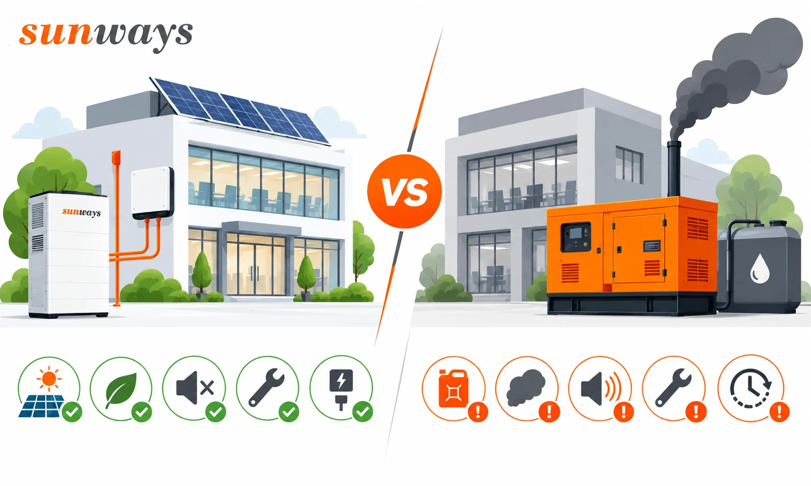
A battery-only backup solution can be considered if the battery is capable of powering critical equipment, covering the target outage duration, and recharging sufficiently before the next power cut. If the power cut is likely to exceed the battery’s runtime and recharging cannot be guaranteed, priority should be given to evaluating diesel generators or a ‘battery plus diesel generator’ solution. Do not decommission existing generators before verifying whether batteries can fulfil the original backup role.
Compare the Three Backup Options
| Your Concerns | Battery Backup | Diesel Generators | Battery + Diesel |
|---|---|---|---|
| Immediately after a power cut | A system with backup capability can switch to power supply; actual duration of the outage must be confirmed | Requires start-up, stabilisation of output and completion of the switchover | Batteries can cover the unit start-up delay, but the entire switchover process must be verified |
| How long can power be supplied? | Depends on available battery charge at the time of the outage, the load and recharging conditions | Depends on fuel, supply, operational level and maintenance arrangements | Power can be supplied initially by the batteries, then taken over or supplemented by the diesel generator, depending on the system design |
| In the event of prolonged or repeated power cuts | Check whether the battery can be recharged between power cuts; utilising photovoltaic power during power cuts requires the appropriate operational capability | Check stock levels, fuel transport, maintenance and on-site operating conditions | Manage battery reserves, generator start-up and shutdown, charging power and fuel supply simultaneously |
| How are costs calculated? | Equipment installation, charging, wastage, maintenance and battery replacement | Equipment installation, actual fuel consumption, fuel transport, maintenance and overhauls | Includes costs for both types of equipment and control integration; fuel-saving percentages advertised cannot be directly applied |
Diesel engines cannot ‘run indefinitely as long as there is fuel’. Standby, prime and continuous operating modes have different conditions of application; load, operating time and maintenance requirements should be verified for each specific unit.
Calculating Runtime from Available Energy
A rough estimate of backup runtime can be calculated as: total electricity available to the load (kWh) ÷ average critical load (kW). Here, the actual amount of electricity available during a power cut must be used, rather than simply applying the battery’s rated capacity.
Assuming that, during a power cut, 120 kWh can be supplied after deducting discharge limits, conversion losses and the system’s own power consumption, with no external recharging during this period. With an average critical load of 30 kW, this energy is sufficient for approximately 4 hours; if the load increases to 60 kW, it will last for approximately 2 hours. This is a set of hypothetical calculations and does not imply that commercial batteries have a standard ‘2–4 hour’ runtime.
The results may vary significantly for the same battery system when powering only lighting and control equipment versus powering an entire refrigeration system. When the actual load varies over time, calculations should be based on electricity consumption during each specific time period. Once the energy calculations have been verified, it is still necessary to check whether the equipment can be started and whether the system can withstand the corresponding output; the next section will explain in detail how to select power and capacity separately.
Do not assume that power cuts always occur when the battery is fully charged. If the battery has already been used for peak shaving during the day, the remaining charge will be reduced; at night, without photovoltaic power, charging may be insufficient even on overcast days. Checking power cut records to identify charging opportunities between multiple outages provides a more comprehensive picture than simply calculating a large battery based on the ‘longest single power cut’.
When a Generator Should Remain Part of the Plan
If a power cut is expected to last longer than the battery can sustain, and solar or grid backup is unreliable, the option of using a diesel generator in conjunction with the system should be retained. The battery can cover part of the critical period, whilst the diesel generator takes over for the remainder and recharges the battery when the equipment permits. Three issues must be clarified in advance for this design.
Firstly, when should the diesel generator be started? It must be triggered in advance based on remaining battery charge, current load and the time required for start-up, allowing for warm-up and retry margins; the start command must not be issued only after the battery has been fully depleted. Victron’s official control documentation specifies settings for remaining charge triggers, time delays, warm-up and cool-down processes; these are operational logic parameters that require configuration, whilst other equipment should be checked to ensure compatibility. Victron Generator Automatic Start-Stop Instructions
Secondly, can the diesel generator supply power and charge the battery simultaneously? Battery charging also draws power from the generator set. If operational loads increase, it must be determined whether the charging power can be reduced or the load adjusted to prevent both tasks from exceeding the generator set’s capacity at the same time.
Third, will critical equipment shut down during the switchover? This should be verified under actual load conditions, including diesel engine start-up, connection, disconnection and grid restoration. For control or IT equipment that cannot tolerate even brief interruptions, a UPS must also be assessed. One must not assume that the entire on-site equipment will definitely not restart based solely on the inverter’s switchover parameters.
When comparing the three options, ensure they are assessed under the same load and backup duration. For diesel generator costs, use fuel consumption records corresponding to the specific load; for battery solutions, use the charging and operational costs associated with the same task. Otherwise, the price comparison may merely be between the different tasks of ‘backing up partial equipment’ and ‘backing up the entire site’.
Commercial Battery Storage Sizing: Can It Carry the Load, and for How Long?
When selecting a commercial energy storage system, it is necessary to determine both power (kW) and capacity (kWh): first, confirm the load the system needs to handle; then calculate the amount of electricity required during the target period; and finally, factor in losses and a reserve for standby power. Monthly electricity bills and installed PV capacity can provide context, but they do not indicate when the load occurs or how long it lasts, and cannot be used directly to determine battery size.
Turn Your Operating Goal into a Load Requirement
Convert the objectives identified earlier into quantifiable inputs. For backup power, list the equipment included in the backup circuit, the conditions under which they operate simultaneously, and the target duration; for peak shaving, specify the maximum power draw from the grid and the periods during which this limit is exceeded; for the transfer of surplus PV power, both the amount of surplus power that can be stored and the subsequent electricity demand that can be met must be assessed. Only then will the calculation reflect the actual workload the battery must handle, rather than simply shifting the entire plant’s electricity consumption into the energy storage system.
The proposal must specify the metering points corresponding to the load curve and ensure these align with the billing time granularity of the electricity supply contract. For equipment start-up, start-up parameters or higher-frequency records should be consulted: minute-level average power may not capture the short-term demand during compressor start-up. The data used to calculate electricity charges and that used to verify start-up capacity may come from different records and cannot be used interchangeably.
Check Power Before Adding More Capacity
First, determine which equipment will operate simultaneously, then check the start-up power and duration of motors, compressors and pumps. Simply adding up the rated power may overestimate the normal load, whilst relying solely on average values may overlook start-up surges. Neither approach is sufficiently reliable.
For example, whilst a compressor may start up without issue on its own, starting it simultaneously with other equipment may exceed the system’s short-term output capacity. You should ask the installer to verify the inverter’s continuous and short-term output, the battery’s permitted discharge power, and the three-phase load distribution simultaneously. If equipment is rated in kVA, this must be assessed in conjunction with the power factor and should not be treated as equivalent to the corresponding kW value.
If the limitation stems from the inverter’s output or the battery’s discharge capacity, simply increasing the kWh rating may not resolve the issue. First identify which component is the limiting factor, then decide whether to adjust the inverter or battery configuration, or—where process conditions permit—stagger the start-up of equipment. Quotations should also distinguish between continuous output and peak output, which can only be sustained for a short period.
Calculate Energy for the Actual Operating Window
Consider a hypothetical peak-shaving task: the grid draws a continuous power of 160 kW during a certain period, and you wish to limit this to 120 kW for 30 minutes. Assume that the load and photovoltaic conditions remain constant during this period.
| Calculation Item | Result |
|---|---|
| Power to be made up by the battery | 160 − 120 = 40 kW |
| Duration | 30 minutes = 0.5 hours |
| Electricity to be supplied to the load during this period | 40 × 0.5 = 20 kWh |
This task requires a continuous supply of 40 kW, totalling 20 kWh. When actual curve variations occur, the electricity required to be supplied during each time period should be calculated separately and then added together. One should not simply look at the figure ‘20 kWh required’ and purchase a battery system with a nominal capacity of 20 kWh.
For a preliminary calculation based on nominal capacity, the following formula may be used: Nominal capacity ≈ electricity required on the load side ÷ (proportion of available capacity for this task × discharge path efficiency). Assuming an available proportion of 80 per cent and a discharge path efficiency of 92 per cent, then 20 ÷ (0.80 × 0.92) ≈ 27.2 kWh.
The figures 80 per cent and 92 per cent are merely assumptions for the calculation; they are not industry defaults, nor are they Sunways specifications. The figure of 27.2 kWh is not the final procurement specification; auxiliary power consumption, temperature, ageing and power limitations must also be verified against the actual product. In particular, it is essential to confirm that the selected configuration can sustainably deliver 40 kW for this half-hour period; power verification must not be overlooked simply because the energy calculation has been passed.
Protect the Reserve and Check the Recharge Window
If the same battery system is used both for day-to-day cost savings and as a backup power source during power cuts, first clarify the committed reserve capacity, then allocate the portion available for day-to-day management.
When comparing capacities, clarify whether the manufacturer is quoting nominal capacity or the capacity available under specified conditions. If depth of discharge (DoD) limits have already been factored in, do not deduct them again; similarly, if the ‘available proportion’ mentioned earlier has already accounted for the standby reserve, do not deduct it a second time. The available energy should also specify whether it is on the battery side or the load side to avoid omitting or double-counting losses.
Finally, check whether the battery can be recharged in a timely manner. For example, if the battery-side energy to be replenished is 60 kWh, but the actual power available for battery charging is only 20 kW, it will take at least 3 hours—even disregarding losses and current limiting during the latter stages of charging. This is a hypothetical ideal lower limit and must not be used as a charging time commitment. A two-hour off-peak window, or a situation where surplus photovoltaic power frequently fails to reach this power level, will affect the next round of operations. When charging via the grid, it is also necessary to check whether this will create new billing peaks.
First, select a system based on critical loads or actual peak-shaving requirements, then assess whether to expand the scope. When requesting a quotation, ensure that the deliverable power, deliverable energy, reserve capacity and conditions for replenishment are clearly specified. Providing only a battery capacity figure in kWh is still insufficient to determine whether the system can fulfil your requirements.
Commercial Battery Storage Cost: What Are You Really Paying For?
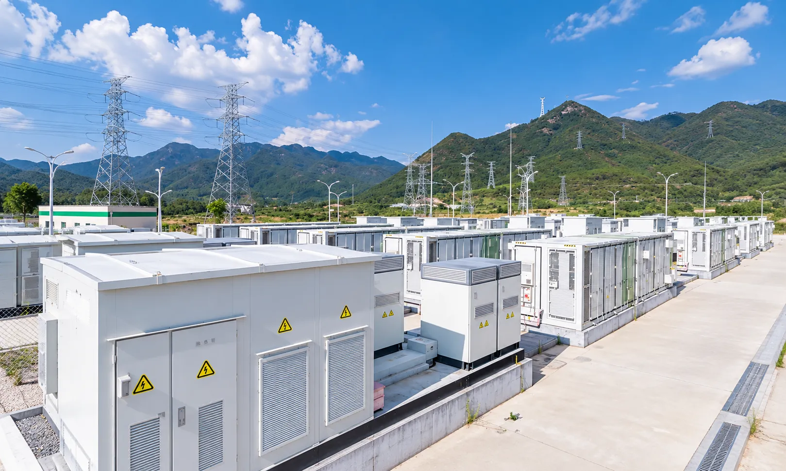
When considering commercial energy storage, you should compare the cost of the complete system as delivered, rather than just the price per kWh of the batteries. Output power, backup capacity, control requirements and on-site installation all affect the total investment. It is not possible to directly determine which of two quotations for the same battery capacity is cheaper if the scope of delivery differs.
Compare Quotes on the Same Scope
When receiving a quote, first confirm: ‘At this price, will the system fulfil the agreed requirements and be ready for use?’ The difference between a price that includes only the battery cabinet and one that includes inverters, electrical distribution modifications and commissioning may not necessarily stem from the cost of the equipment itself, but could also result from omitted items.
| Quote Section | What Should Be Clearly Stated | What Is Easily Overlooked When Comparing |
|---|---|---|
| Location and Pricing Basis | Country, currency, quote date, taxes and duties, transport and delivery terms | Differences arising from varying dates, exchange rates and tax treatment |
| Batteries | Nominal/usable capacity, operating conditions, warranty scope | Definition of usable capacity, degradation conditions and warranty limitations |
| Inverters/PCS | Continuous output, short-term output, backup power functionality and scope | Mistaking peak output for continuous output, or assuming that backup power equipment is already included |
| Control and Protection | BMS, EMS, metering, isolation and essential ancillary equipment | Software licensing, communication access and control integration costs |
| Installation and Delivery | Power distribution retrofitting, on-site engineering, grid connection, commissioning and acceptance | Costs for sites not surveyed are treated as part of a fixed lump sum |
| Subsequent Use | Service subscriptions, maintenance, repairs, replacements and warranty scope | Only initial capital expenditure is compared; subsequent cash outlays are not considered |
When it comes to factory refurbishment, the schedule for construction-related downtime should also be clearly set out. A low equipment quotation that requires a longer period of downtime may not necessarily represent the option with the lowest total cost for you. Costs that have not yet been assessed should be listed as provisional estimates, with an explanation of the circumstances that could lead to changes.
Industry-wide price trends can provide context but cannot replace local quotations. According to a report published by IRENA in 2025, the total installation cost of large-scale battery energy storage projects fell by approximately 93 per cent between 2010 and 2024. This is a historical statistic for utility-scale projects; it does not represent the installation cost for a specific factory in India, Pakistan or Europe, nor should it be used to estimate your payback period.
IRENA, Renewable Power Generation Costs in 2024, Executive Summary, page 9
Test the Payback Before Approving the Investment
First calculate the annual net savings; only then should you discuss the payback period. The benchmark for comparison should be the difference in cash outlay between ‘no storage’ and ‘with storage’ under identical electricity demand and PV conditions. When adding batteries to an existing PV system, the savings that the PV system would have generated anyway must not be counted as benefits of the battery.
Peak shaving should be calculated according to actual billing rules, whilst peak-to-off-peak shifting should account for charging costs, losses and auxiliary power consumption; when storing surplus solar power, the foregone revenue from electricity sales must also be taken into account. Maintenance, servicing and other additional costs should be deducted from the benefits. Multiple uses may be combined, but must be calculated within the same dispatch plan to avoid double-counting the same cost or attributing benefits to tasks that cannot be completed simultaneously.
As a preliminary assessment, the following formula may be used: Simple payback period = Total initial investment ÷ Positive annual net savings. If the annual net savings are not positive, there is no finite payback period calculated in this manner; if annual returns vary significantly, cash flows should be accumulated year by year, rather than dividing by the first year’s returns as a fixed value.
The following is a purely mathematical example to illustrate this. Assume the total initial investment is €100,000, with annual additional costs for maintenance and services amounting to €4,000. The reduction in the bill per operating day is assumed to take into account changes in charging costs, wear and tear, auxiliary electricity consumption and revenue from electricity sales.
| Scenario | Number of Operating Days per Year | Reduction in Bill per Operating Day | Annual Net Savings | Simple Payback Period |
|---|---|---|---|---|
| Conservative | 200 days | €80 | 200 × 80 − 4,000 = €12,000 | approx. 8.3 years |
| Baseline | 240 days | €100 | 240 × 100 − 4,000 = €20,000 | 5 years |
| Favourable | 250 days | €116 | 250 × 116 − 4,000 = €25,000 | 4 years |
This illustrates that the payback period for the same investment can vary significantly depending on operational opportunities and fluctuations in daily revenue. For real-world projects, the daily figures in the table cannot be applied directly; calculations should be based on local electricity prices, actual dispatched power volumes and demand charges.
Which Commercial Battery Inverter Fits Your System? Look Beyond the Nameplate
When selecting an inverter or PCS based on system architecture, battery operating range and load requirements, one must not focus solely on the AC rated power. Even for equipment both rated at 30 kW, it is only when matched with the appropriate batteries, operating conditions and supporting systems that one can determine whether it is capable of fulfilling your project’s requirements.
Match the Inverter’s Role to the System
Hybrid inverters can integrate both PV and battery systems into a single unit; standalone battery inverters or PCS units are primarily responsible for power conversion between the battery and the AC system. Once the type has been determined, it is essential to clarify which devices are responsible for dispatch, metering and protection, and to avoid assuming that a designation such as ‘hybrid’ or ‘energy storage’ encompasses the full range of functions.
If backup power is required, the solution should specifically list off-grid operation, isolation and switching configurations, as well as the actual backup power circuits to be connected. The ability to charge and discharge whilst connected to the grid does not necessarily mean the system can supply power during a power cut. Furthermore, the inverter’s conversion efficiency cannot be directly equated with the round-trip efficiency of the complete system: the latter also involves the battery, other conversion stages and auxiliary power consumption.
Why a 30 kW Rating Does Not Tell the Whole Story
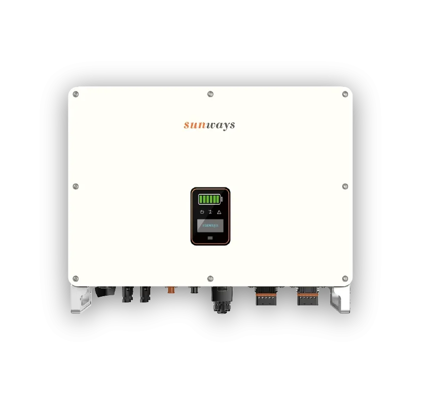
Taking the Sunways STH-30KTL-HT as an example, the following parameters must be considered in conjunction.
| Official Parameter | Specified Value | What You Need to Assess Based on This |
|---|---|---|
| Rated Output Power — Grid | 30,000 W | The AC grid-connected rated output |
| Battery Voltage Range | 200–800 V | Whether the battery’s operating voltage falls within the permitted range |
| Max. Charge/Discharge Current | 80/80 A | The charge and discharge currents each have their own independent upper limits |
| Battery Communication Mode | CAN / RS485 | Further verification of specific protocols, models and compatibility documentation is required |
Assuming the battery terminal voltage is 200 V, and both the battery and the inverter allow a discharge current of 80 A, the DC-side power is 200 × 80 = 16,000 W, or 16 kW, before conversion losses are taken into account. This calculation illustrates that: a 30 kW AC rated power does not mean that the battery can continuously supply 30 kW on its own across its entire permissible voltage range.
This is a mathematical explanation based on the upper limit of the specifications, not a measured output. Actual discharge capacity may also be limited by the Battery Management System (BMS), battery cells, temperature and state of charge; when photovoltaic power is also contributing to the supply, the total system power requires separate analysis.
Therefore, suppliers should confirm how much power the battery can provide within the intended operating range, rather than merely stating that its voltage ‘falls within the permitted range’.
Confirm Compatibility Before You Order
The mere presence of a CAN or RS485 interface is not sufficient proof that a particular battery is compatible. Before placing an order, you will need manufacturer documentation specifying the exact model, communication protocol and firmware version. Compatibility checks should cover the following six points, rather than simply verifying whether the connectors fit.
| Check Item | Confirmation Required from the Supplier |
|---|---|
| Voltage Range | Whether the battery meets the inverter’s requirements within its intended operating range |
| Permissible Current | The maximum charge and discharge currents permitted by the BMS and the battery at the target temperature and state of charge |
| Model, Protocol and Firmware | Evidence of compatibility corresponding to the specific battery model, inverter model, protocol and required version |
| Load Support | Whether continuous power, start-up requirements, three-phase distribution and power factor are compatible |
| Isolation and Control | How isolation, switching and dispatch are implemented during grid connection, power outages and power restoration |
| Local Connection Documentation | Connection and certification documents corresponding to the actual model, configuration and project location |
It is recommended that key operating conditions be included in the commissioning and acceptance plan, such as simultaneous equipment start-up, backup power switching, and operation when the battery is at an agreed low state of charge. It should be clarified in advance which aspects can be verified through document review and which require on-site validation. The parameter examples provided in this document do not imply that this model is automatically compatible with all target markets or all battery types.
Before placing an order, you will need a clear confirmation of the configuration: which inverter is paired with which battery, what tasks are to be performed under what conditions, and how these will be verified during acceptance testing. This transforms ‘theoretical support’ into verifiable delivery requirements.
Your Next Step: Choose the Route That Fits Your Site
First select a route based on site conditions, then determine the system size. If existing PV equipment remains suitable, first compare the option of retrofitting the retained equipment with AC coupling, confirming that power distribution, control and the required backup power functions can be achieved, before deciding whether to replace the inverter. When installing new PV and energy storage systems together, incorporate a hybrid inverter solution into the design as early as possible to avoid discovering mismatches between the battery and output power only after procurement has been completed.
If power cuts are likely to exceed the battery’s runtime and there is no certainty of a power supply, prioritise evaluating diesel generator or battery-plus-diesel generator solutions. If cost savings are only valid under favourable assumptions and there is insufficient backup power demand to justify the investment, postpone procurement for the time being; instead, gather additional electricity consumption data, adjust operating modes or scale down the system. Do not accept unsubstantiated payback period promises simply to place an order as quickly as possible.
When preparing to commence project evaluation, collate information on the project’s location and context, existing PV and inverter configurations, time-of-use electricity consumption records, electricity bills, as well as the equipment that must be retained and the target backup duration. For sites with diesel generators, you should also prepare details of the generator model, fuel consumption under corresponding loads, and power outage records. Armed with this information, familiarise yourself with Sunways’ commercial and industrial energy storage solutions; subsequent discussions can then focus on system configurations, budgets and scope of delivery that are suitable for the specific site.
Start Your Project