What Is an Energy Management System(EMS)?
Table of Contents
An Energy Management System (EMS) is an intelligent management platform that integrates hardware and software. It monitors data from photovoltaic (PV) generation, energy storage batteries, the electricity grid and loads in real time, and coordinates energy flows based on electricity tariffs, energy demand and equipment status. By optimising battery charging and discharging and system operation, the EMS can increase the proportion of self-consumption of PV-generated electricity, reduce electricity costs and enhance the operational reliability of the energy system.
What Is an Energy Management System?
The term ‘energy management system’ has two common meanings: one refers to an energy management system at the organisational level, whilst the other refers to a digital system used to monitor, analyse and control energy equipment. Both aim to improve energy performance, but they differ in terms of what they manage, how they operate and the contexts in which they are applied.
Organizational Energy Management System
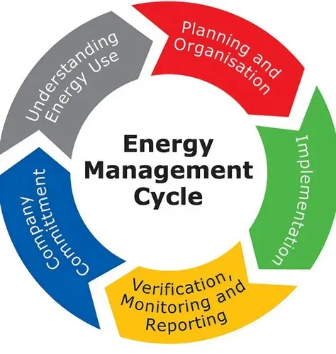
An organisational energy management system is commonly abbreviated to EnMS. It centres on management systems, staff responsibilities and continuous improvement processes, rather than any specific software or hardware product.
ISO 50001 provides a systematic framework for organisations to establish, implement, maintain and improve their EnMS. Organisations typically need to formulate an energy policy, identify key areas of energy use, and set energy objectives, energy baselines and energy performance indicators. Subsequently, through monitoring, auditing and improvement measures, organisations continuously enhance energy efficiency and reduce unnecessary energy consumption.
Consequently, an EnMS as defined by ISO 50001 is more akin to a corporate energy governance approach. Whilst it may utilise data provided by software, it is not in itself equivalent to a monitoring platform, nor does it directly control inverters or energy storage batteries.
Digital Energy Management System
Digital energy management systems are commonly referred to as EMS. They consist of energy equipment, metering devices, communication components, data services and software platforms, and are used to collect, analyse and manage actual energy flows.
The US Department of Energy describes an Energy Management Information System (EMIS) as a type of system comprising equipment, data services and software applications. These systems are capable of centralising energy data and are used to monitor, analyse and control energy usage and equipment performance.
In photovoltaic and energy storage applications, a digital EMS typically connects to:
- photovoltaic inverters;
- energy storage batteries and BMS;
- smart meters;
- the electricity grid;
- electrical loads;
- charging points or other controllable devices.
The system first collects data on power generation, electricity consumption, battery SOC, electricity purchases and feed-in to the grid. It then formulates operating strategies based on electricity tariffs, load requirements, equipment status and user objectives. For example, the EMS can schedule battery charging and discharging, increase the rate of self-consumption of PV power, reserve backup power, or limit the power output from the system to the grid.
Platforms that merely display data are closer to energy monitoring systems; systems capable of analysing data and coordinating equipment according to operational objectives are more in line with the full meaning of a digital EMS.
Organizational EnMS vs Digital EMS
| Comparison | Organisational EnMS | Digital EMS |
|---|---|---|
| Scope of management | Corporate policies, personnel and energy performance | Energy equipment, data and energy flows |
| Core approach | Policies, objectives, audits and continuous improvement | Monitoring, analysis, strategies and equipment control |
| Typical Outputs | Energy targets, performance indicators, improvement plans | Energy flow data, alerts, reports and control commands |
| Is it software? | Not a single software product | Usually comprises software and hardware |
| Main Applications | Corporate energy governance, ISO 50001 management | Photovoltaics, energy storage, buildings, factories and microgrids |
| Relationship between the two | Can utilise data provided by digital EMS | Can provide data and execution tools for organisational EnMS |
Why Do Solar and Battery Systems Need an EMS?
Photovoltaic and energy storage systems require an energy management system: power generation, energy storage, electricity consumption and grid interaction must be coordinated and operated as a single integrated system; individual devices cannot be allowed to operate independently over the long term.
Solar power generation is intermittent, loads fluctuate constantly, and battery capacity is limited. Only by using an EMS to centrally collect data and implement strategies can the system strike a balance between cost-effectiveness, reliability and operational efficiency.
Without an EMS, PV inverters, batteries, smart meters and loads can still operate independently. However, the system is often limited to basic power generation and charging/discharging functions, and struggles to proactively adjust in response to real-time electricity prices, load fluctuations and backup power requirements.
1. Energy Data Is Scattered Across Different Devices
A PV-storage system typically comprises a PV inverter, energy storage batteries, a battery management system (BMS), a smart meter and other components. The data generated by these devices is not entirely consistent.
The inverter records PV generation, the BMS records the battery’s state, the electricity meter measures electricity purchased and fed into the grid, whilst the load side reflects actual electricity demand.
If data is scattered across different devices and platforms, it is difficult for users to know where surplus PV electricity is going or whether the system is feeding electricity into the grid.
The primary value of a solar energy management system lies in transforming fragmented data into a comprehensive, understandable energy flow. By unifying the data, users are no longer limited to viewing the status of a single device, but can understand how the entire system operates.
2. Battery Charging and Discharging Require Coordinated Control
The charging and discharging of battery banks must also take into account the current State of Charge (SOC), future PV generation, current and projected loads, and peak-off-peak electricity tariffs, amongst other factors.
For example, in markets with time-of-use tariffs, it may be appropriate to charge batteries during off-peak hours and discharge them during peak hours. However, if strong sunlight is forecast for the following day, charging the batteries to full capacity from the grid overnight may occupy capacity that would otherwise be used to store surplus solar power.
Therefore, the battery energy management system (EMS) must schedule battery operations in accordance with the objectives of the entire energy system. The EMS’s control must comply with the safety constraints set by the battery management system (BMS). The BMS determines whether the battery can be safely charged or discharged at any given time, whilst the EMS determines which strategy the system should adopt within safe limits.
3. System Faults Are Often Discovered Too Late
Many PV systems do not shut down completely immediately when a fault occurs. If reliance is placed solely on manual checks, problems may only be detected days or even longer after they arise. An EMS can continuously monitor equipment status and operational data. When the system detects an anomaly, it can generate alerts and provide relevant historical information to help operations and maintenance (O&M) personnel identify the source of the problem more quickly.
4. Multiple Solar and Storage Sites Are Difficult to Manage Separately
A single residential project can be managed via a single app, but installers, distributors and O&M teams typically need to manage dozens, hundreds or even more sites. An EMS for solar and storage should provide centralised multi-site management capabilities, allowing users to view project status, alerts, power generation and equipment information on a single platform.
5. Electricity Tariffs Are Becoming More Complex
In the past, many users only needed to be concerned with their total electricity consumption. Now, an increasing number of projects must also take into account peak, off-peak and night-time tariffs, dynamic pricing, and the difference between grid purchase and sale prices. In such circumstances, fixed charging and discharging schedules are often insufficiently flexible. Energy management strategies must be configured according to tariff structures and project objectives, rather than applying a single model to all systems.
How an EMS Addresses These Challenges
| Customer Issues | EMS Solutions | Practical Value for Users |
|---|---|---|
| Dispersed PV, battery and load data | Centralised collection and display of energy data | A clearer understanding of system energy flows |
| Uncertainty regarding battery charging and discharging times | Automatic execution of charging and discharging strategies | Increased self-consumption rates and optimised electricity bills |
| Faults detected too late | Real-time alerts and remote diagnostics | Shorter fault response times |
| Difficulty managing multiple projects | Centralised management of multiple sites | Reduced O&M and after-sales costs |
| Complex electricity tariff structure | Time-of-use tariffs, peak-shaving and backup power strategies | Improved cost-effectiveness of energy use |
How Does an Energy Management System Work?
The Energy Management System operates through five consecutive steps: ‘monitoring, analysis, decision-making, control and verification’. It first collects data from photovoltaic systems, batteries, the grid and loads; then formulates strategies based on equipment status, electricity tariffs and user objectives; subsequently sends instructions to controllable devices; and continuously adjusts these strategies based on actual results.
a. Monitor Energy Data
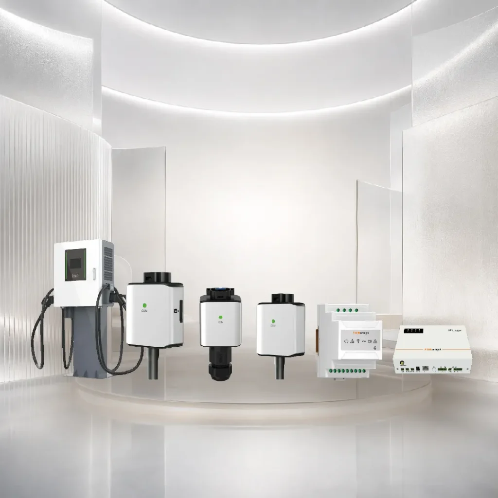
The first step in the EMS is to acquire accurate, continuous and time-stamped operational data. Data typically originates from inverters, BMS units, smart meters, data loggers and other sensing devices. Smart meters play a vital role in this process. They are usually installed at the grid connection point to determine whether the system is currently drawing power from the grid or feeding power into it.
The quality of data collection directly impacts subsequent decision-making. If the meter is incorrectly positioned, the current transformer (CT) is wired in the wrong direction or there are delays in communication data, the EMS may produce erroneous results even when using the most sophisticated algorithms. A reliable EMS must first and foremost be built upon accurate metering and stable communication.
B. Analyse Operating Conditions
Once the data has been collected, the EMS analyses the current system status and determines how energy is flowing. This includes, for example, real-time energy flows between PV, batteries, the grid and loads; daily load profiles and peak electricity consumption; current and historical maximum power demand; and so on.
A battery’s ‘available capacity’ is not equivalent to the total capacity stated on the nameplate. The EMS must also take into account the current State of Charge (SOC); minimum and maximum SOC settings; the charge and discharge power permitted by the Battery Management System (BMS); and the reserved backup capacity.
For example, for a battery with a nominal capacity of 10 kWh, if 20 per cent must be reserved as backup power, whilst also subject to SOC limits and system efficiency constraints, the actual amount of energy available for economic dispatch will be less than 10 kWh.
c. Select an Energy Strategy
Once the analysis is complete, the EMS selects an operating strategy based on the project objectives. For example, whether the battery should be charged or discharged at that moment, what charging and discharging power levels should be used, and whether feed-in to the grid needs to be restricted. A good EMS does not simply choose the cheapest operation at every moment, but rather strikes a reasonable balance between safety, reliability and economic efficiency.
d. Control Connected Devices
Once the strategy has been determined, the EMS sends operating commands to controllable devices (inverters, energy storage batteries, EV charging points, generators, and adjustable loads). This includes setting battery charging and discharging power levels; adjusting the minimum reserve SOC; and limiting inverter output.
Smart meters are typically responsible for measurement and feedback, rather than being the primary devices directly controlled by the EMS. The EMS reads data from the smart meter to determine whether the control commands have achieved the intended effect. In zero-feed-in mode:
- The smart meter detects that the system is feeding power into the grid;
- The EMS reads this data;
- The EMS reduces the inverter output or increases the battery charging power;
- The smart meter measures the power at the grid connection point again;
- The EMS continues to fine-tune until the feed-in power approaches the target value.
e. Verify and Adjust
After sending control commands, the EMS must also verify the actual results. The system continuously compares the target charge and discharge power with the actual power, as well as the set feed-in upper limit with the actual feed-in power. If there is a deviation from the target, the EMS re-analyses the situation based on the latest data and adjusts the commands accordingly. However, whilst cloud platforms are suitable for remote monitoring, analysis and management, safety protection and critical real-time control should, as far as possible, remain at the device level or within the local control layer.
What Are the Main Components of an EMS?
A comprehensive energy management system typically comprises the device layer, the communication layer, the local control layer and the cloud application layer. These four layers are responsible, respectively, for energy generation and metering, data transmission, real-time control and remote analysis.
| System Layer | Typical Components | Main Functions |
|---|---|---|
| Device Layer | Inverter, battery, BMS, smart meter, EV charger | Power generation, energy storage, power consumption and measurement |
| Communication Layer | Data logger, gateway, RS485, CAN, Ethernet | Data acquisition, conversion and transmission |
| Local Control Layer | Local EMS, controller, microgrid controller | Execution of local policies and real-time control |
| Cloud/Application Layer | Web portal, app, cloud platform | Remote monitoring, analysis and multi-site management |
1. Device Layer
The device layer forms the basis for the EMS to acquire real-time operational data and execute control commands.
Photovoltaic inverters are responsible for converting the direct current generated by the modules into alternating current. Energy storage batteries are responsible for storing and releasing energy. The Battery Management System (BMS) monitors the state of the battery cells and prevents unsafe charging and discharging behaviour. Smart meters measure the power purchased, fed into the grid and consumed at the grid connection point.
The quality of data at the device layer is of paramount importance. Even the most advanced energy management system software cannot compensate for incorrect on-site metering or device configuration.
2. Communication Layer
The communication layer is responsible for transmitting data from different devices to a local controller or cloud platform.
Some common components and communication methods include:
- Data logger;
- Communication gateway;
- RS485;
- CAN;
- Modbus;
- Ethernet;
- Wi-Fi;
- Cellular network.
Different devices may use different protocols. The role of the communication gateway is to uniformly collect device data and convert it into a format recognisable by the EMS. The communication layer not only affects whether data can be uploaded but also influences the system’s response speed. Critical energy control should not rely entirely on a public internet connection. In the event of a network outage, basic control and safe operation should continue to be carried out by local devices.
3. Local Control Layer
The local control layer is responsible for implementing energy strategies and real-time control at the project site. It typically reads data from inverters, batteries, smart meters and loads, and sends control commands based on pre-set strategies.
The key benefits of the local control layer are response speed and operational continuity. In zero-feed-in control, the system needs to continuously monitor the power at the grid connection point and rapidly adjust the power output of the inverters or batteries. If all data were first uploaded to the cloud, only to await instructions in return, network latency and interruptions could compromise control effectiveness. A sound EMS architecture typically places real-time control locally, whilst reserving remote analysis and management for the cloud.
4. Cloud and Application Layer
The cloud application layer is responsible for transforming device data into intuitive, actionable information, enabling users to remotely monitor and manage the entire energy system. Its common functions include:
- Real-time Monitoring: Real-time viewing of PV generation, battery SOC, electricity purchase and feed-in to the grid, load consumption, equipment status and overall energy flow.
- Historical Analysis: Calculates daily, monthly and annual generation figures; analyses load curves, battery charge and discharge records, peak demand, self-consumption rates and long-term operational trends.
- Smart Alerts: Promptly sends alerts to end users, installers or O&M personnel when equipment goes offline, communication is interrupted or operational anomalies occur.
- Remote O&M: Supports remote viewing of faults, operating parameters and historical data. Some platforms also allow for remote configuration, diagnostics and software updates.
- Multi-site Management: Enables installers, distributors, O&M teams and commercial and industrial groups to centrally manage multiple projects on a single platform.
- User Permission Management: Assigns different data and operational permissions based on roles such as manufacturers, distributors, installers, O&M providers, project owners and end users.
Is an EMS Hardware or Software?
An EMS comprises both hardware and software. The hardware is responsible for energy data measurement, equipment communication, local control and command execution; the software handles data visualisation, trend analysis, anomaly alerts, policy configuration, user permission management and remote operation and maintenance. Only when the hardware and software work in tandem can the EMS complete the full closed-loop process from data acquisition to equipment control.
Energy Monitoring System vs Energy Management System
An energy monitoring system is responsible for informing users of ‘what is happening within the system’, whilst an energy management system not only views the data but also determines ‘how the system should operate next’ based on set objectives. Both handle energy data, but the real difference lies in whether they possess the capabilities for policy calculation, equipment control and feedback on results.
| Function | Energy Monitoring System | Energy Management System |
|---|---|---|
| Real-time data | ✓ | ✓ |
| Historical records | ✓ | ✓ |
| Fault alerts | Usually supported | ✓ |
| Energy analysis | Basic or limited | ✓ |
| Battery control | Usually not supported | ✓ |
| TOU strategy | Usually not supported | ✓ |
| Peak shaving | Usually not supported | ✓ |
| Multi-device coordination | Limited | ✓ |
Energy Monitoring System: Collection and Display of Operational Data
The Energy Monitoring System displays photovoltaic generation, battery State of Charge (SOC), electricity purchased from and fed into the grid, load power, equipment status and historical trends. Users can use this data to determine whether the system is currently operating normally; however, the platform does not typically proactively alter the operating mode of the inverter, battery or load.
Energy Management System: Adding Analysis, Strategy and Control Capabilities to Monitoring
The EMS combines electricity tariffs, load, PV generation, battery status and user objectives to determine when to charge or discharge the battery, whether to reserve backup capacity, whether to limit feed-in, and whether to implement peak-shaving strategies.
Consequently, the core value of the EMS lies not in providing more charts, but in transforming data into actionable operational strategies and implementing control via connected devices.
Suppose a commercial or industrial project currently has a load of 180 kW, PV generation of 70 kW, grid power consumption of 110 kW, and a battery SOC of 65 per cent. An energy monitoring system can display this data to the user, but typically does not make further adjustments to system operation.
The EMS, however, will go on to assess whether grid power is approaching the set peak threshold, whether the battery has sufficient available capacity, and whether the BMS permits discharge. If the conditions are met, the EMS will send a discharge command to the energy storage equipment and continue to read data from the smart meter until the grid-side power falls within the target range.
Residential EMS vs C&I EMS
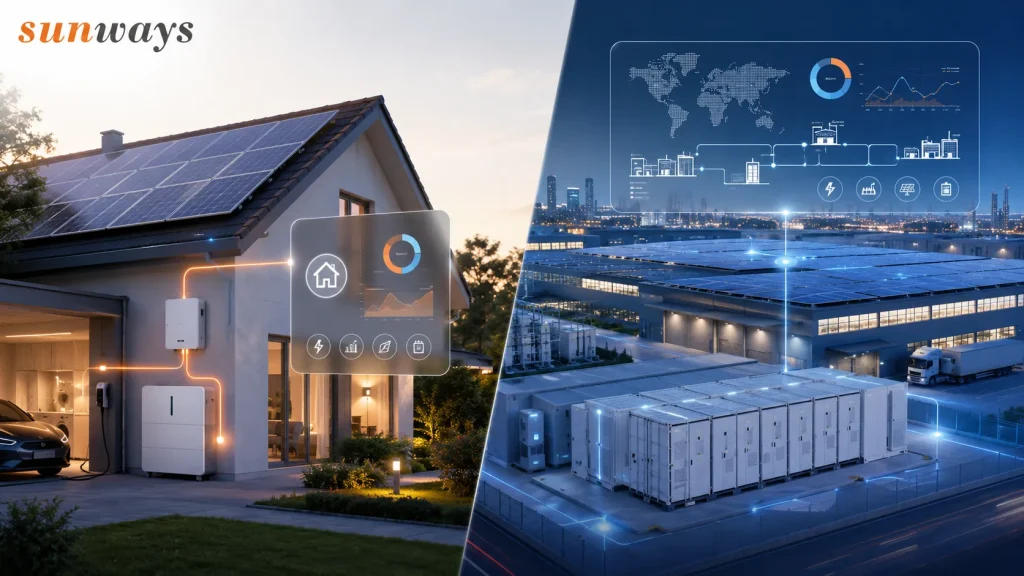
Home EMS primarily serves single-family homes, with a focus on increasing the self-consumption rate of solar power, reducing household electricity bills and maintaining backup power; C&I EMS is aimed at factories, industrial estates and commercial buildings, placing greater emphasis on peak shaving, demand management, multi-device coordination and return on investment.
| Comparison | Home EMS | C&I EMS |
|---|---|---|
| Primary users | Homeowners, residential installers | Factories, EPCs, energy managers, O&M teams |
| Primary objectives | Increasing self-consumption rates, reducing electricity bills, providing backup power during outages | Peak shaving, demand management, ROI, supply reliability |
| Scale of Management | Single dwelling or a small number of household devices | Multiple devices, circuits and sites |
| Common Strategies | Self-consumption, TOU, backup reserve | Peak shaving, load shifting, demand control |
| Primary Interfaces | Mobile app, simplified web page | Web portal, dashboard, centralised management platform |
| Key Data | PV, battery, grid, household load | PV, ESS, meter, generation load, site demand |
| Control Complexity | Relatively simple | High; typically requires local control and multi-tiered permissions |
| Key Decision Metrics | Household electricity bills, self-consumption rate, SOC | Peak power, demand charges, ROI, equipment availability |
Home Energy Management System
A home energy management system typically connects a residential photovoltaic (PV) system, energy storage batteries, household loads, the electricity grid and an EV charging point. Users can view power generation, electricity consumption, battery State of Charge (SOC) and electricity purchases via an app, and set modes such as self-generation for self-consumption, time-of-use pricing or backup power.
The core objective of a residential EMS is to enable households to utilise as much of the solar energy they generate as possible. For example, during the day, the PV system prioritises supplying the home’s loads, with surplus electricity used to charge the battery; at night or during periods of high electricity tariffs, power is supplied from the battery, thereby reducing the amount of electricity purchased from the grid.
In areas prone to frequent power cuts or with an unstable grid, a Home EMS must also manage a minimum reserve SOC. The battery is not fully discharged for the sake of short-term savings on electricity bills, but rather retains a certain capacity for use by critical loads.
Residential users generally do not require complex industrial-grade reports. They are more concerned with whether the interface is clear, whether energy flows are intuitive, and whether battery strategies are easy to configure. Therefore, an excellent Home EMS should conceal complex controls behind simple operations.
To learn more about residential PV, hybrid inverters and home energy storage configurations: Sunways Residential Solar Solutions.
Commercial and Industrial Energy Management Systems
Commercial energy management systems are designed for settings such as factories, warehouses, shopping centres, hospitals and industrial estates. Industrial energy management systems generally fall within this scope as well, but place greater emphasis on production loads, continuous power supply and equipment operational reliability.
C&I projects involve larger scales of electricity consumption and more complex load variations. The system may simultaneously connect solar inverters, commercial and industrial energy storage systems, multiple smart meters, production equipment, EV charging facilities and even generators. A C&I EMS must not only monitor total electricity consumption but also analyse peak demand, production load curves, available energy storage capacity and time-of-use electricity tariffs.
For enterprises with multiple sites, a C&I EMS should also support multi-site management. C&I systems involve a greater number of devices and carry higher control risks. Consequently, key strategies typically need to be executed by local controllers, whilst the cloud platform handles data analysis, remote operation and maintenance, and multi-site management. Relying solely on cloud connectivity for real-time peak shaving or anti-reverse-flow protection is not a sound system architecture.
Find out more about C&I EMS:
How Sunways Cloud Supports Smarter Solar and Energy Management?
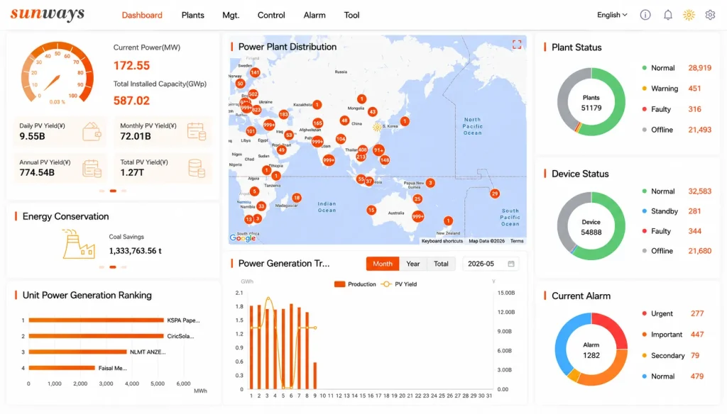
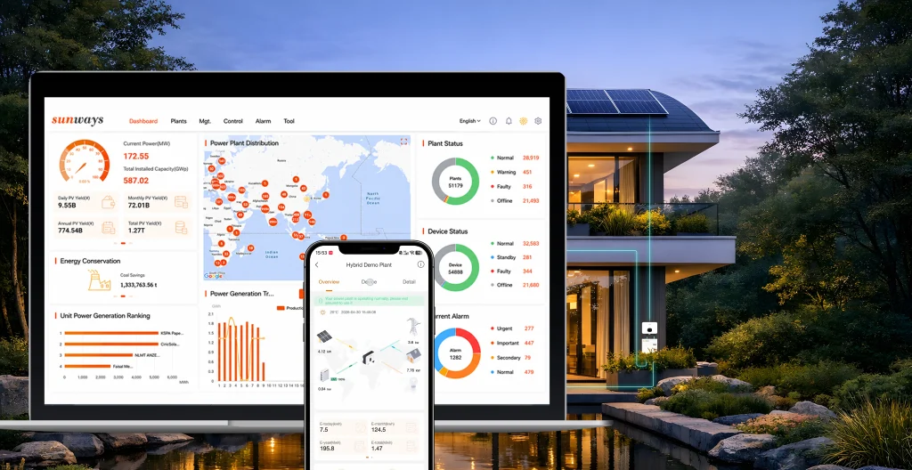
Sunways Cloud (Sunways Portal) is Sunways’ cloud-based monitoring and energy management platform for residential, commercial and industrial PV systems. It consolidates data from power plants, inverters, energy storage systems and operational metrics into a single interface, helping end users monitor their energy consumption whilst also facilitating multi-site management and remote services for installers, distributors and O&M teams.
The Sunways Portal not only displays the current and historical operational status of solar installations, but also offers functions such as alerts, data analysis, diagnostics, equipment maintenance, reporting and remote parameter management.
Real-time Energy Visibility
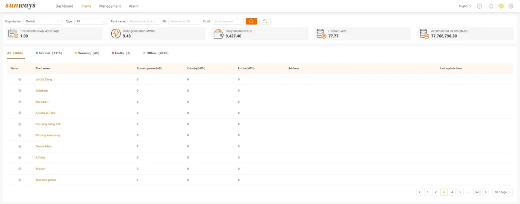
Sunways Cloud brings together data from various devices and presents it in a centralised view. Users can view the operational status of their solar installations, real-time power output, cumulative energy generation, equipment status and current alerts. Once hybrid inverters, energy storage batteries and smart meters have been configured, the platform can also display battery status, grid interaction, load consumption and system energy flows.
For residential users, this visualisation helps them determine whether their home is currently drawing power primarily from the PV system, the battery or the grid. For installers and energy managers, the unified data interface reduces the time spent checking individual devices.
The platform’s Dashboard also summarises the power plant’s generation, electricity consumption, revenue, equipment status and environmental benefits, and allows users to view generation statistics by day, month, year and across the project’s entire lifecycle.
Historical Data and Reports
In addition to real-time data, Sunways Cloud also supports the retrieval and download of historical operational information. Users can search for data by equipment serial number, project name and time range, and generate equipment or power plant reports. Historical data can be used to analyse variations in power generation, equipment operating trends, electricity consumption and revenue, amongst other factors.
Remote O&M
Sunways Cloud enables authorised users to remotely view equipment status, operational data, alarms and parameters. The platform also offers remote start/stop, restart and parameter configuration functions for certain equipment, thereby reducing the need for some on-site operations.
Remote control does not mean that all users can modify equipment parameters at will. Grid connection standards, protection settings and equipment operating modes affect system safety and must be managed by suitably qualified personnel in accordance with local grid regulations.
Smart Alerts
The platform can centrally display equipment alerts from different power stations. Users can filter by equipment, alert level, alert status and time range, and can also export alert logs.
Users can also configure whether to receive alerts and select appropriate notifications based on urgency. In this way, installers and O&M personnel do not have to wait until customers notice abnormalities in power generation before taking action; instead, they can identify equipment going offline, communication faults or operational failures at an earlier stage.
A good alerting system does more than simply display error codes. It should help O&M personnel quickly identify the affected power station, equipment and time of the fault, thereby reducing resolution times.
Multi-site Management
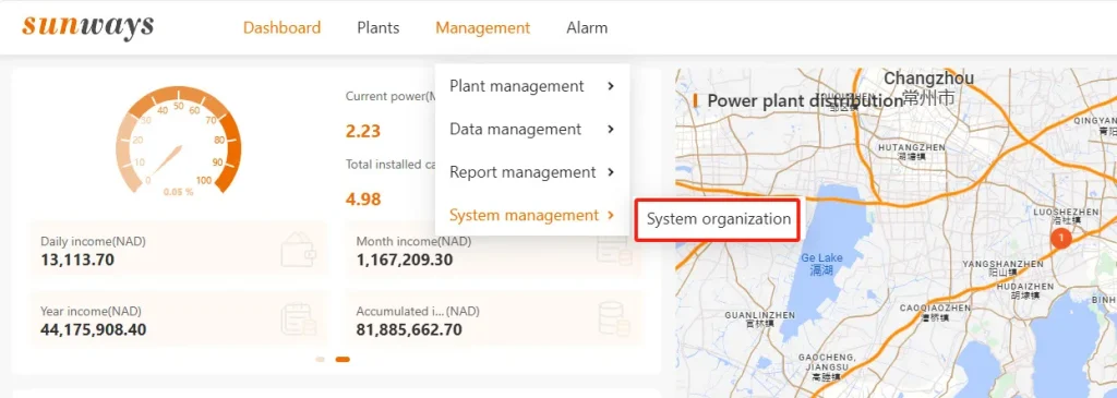
Sunways Cloud enables users to view the locations, operational status and alerts for multiple power stations via lists and maps. Installers, distributors and O&M teams can manage multiple projects under a single account system, without having to log in to different systems individually. The platform provides a centralised overview of information such as the number and locations of power stations, as well as reports on power stations and equipment.
For organisations with a large number of distributed projects, multi-site management offers greater practical value than simple single-site monitoring. It enables teams to prioritise projects with genuine anomalies, rather than manually checking all power stations on a daily basis.
Multi-level User Management
Sunways Cloud supports the management of organisations, sub-organisations and accounts with different roles. Distributors can create subordinate organisations or internal accounts, and configure user identities, organisational affiliations and access permissions for different users.
Energy Strategy Management
For hybrid inverters and energy storage systems that support the relevant functions, Sunways Cloud is not merely a solar monitoring platform; it can also be used to configure certain energy operation strategies.
Relevant functions include:
- General Mode: PV generates power to supply the load as a priority; surplus electricity charges the battery before being fed into the grid;
- Economic Mode: Suitable for scenarios where the difference between peak and off-peak electricity prices is significant;
- UPS Mode: Prioritises maintaining battery charge to supply backup loads during a power cut;
- Off-grid Mode: PV and the battery jointly supply power to off-grid loads;
- Peak Load Shifting: When the load exceeds a set power level, the battery discharges to reduce peak demand on the grid;
- Export Limitation: Limits the power exported by the system to the public grid;
- SOC Protection: Sets the depth of battery discharge and protection limits for both grid-connected and off-grid modes.
The availability of these strategies depends on the inverter model, energy storage configuration, software version, account permissions, local regulations and the specific scope of the contract. Features such as dynamic pricing, VPP and third-party APIs should also be described separately in accordance with officially launched markets and product versions; they cannot be assumed to be supported by default for all users.
From Monitoring to Energy Management
Sunways Cloud is primarily a monitoring platform for photovoltaic and energy storage systems; it also provides remote operation and maintenance, parameter configuration and energy strategy management capabilities for supported devices. Only when Sunways Cloud is integrated with Sunways inverters, energy storage systems, smart meters and local control functions can a complete system be established, ranging from data acquisition to remote management.
FAQs About Energy Management Systems
Q1. What is an EMS, or Energy Management System?
EMS stands for Energy Management System. It first collects data from inverters, batteries, smart meters and loads, then analyses the system status and implements appropriate energy strategies. A comprehensive EMS is not merely a data display platform; it should also be capable of strategy configuration, device control and feedback on results.
Q2. What is a Home Energy Management System?
A home energy management system (HEMS) is a system used for monitoring and controlling residential energy. It typically connects to rooftop solar panels, home batteries, the electricity grid, domestic loads and EV charging points. Users can view energy flows, battery State of Charge (SOC) and electricity purchases via an app, and set modes such as self-generation for self-consumption, time-of-use pricing or backup power. The focus of a HEMS is to reduce household electricity bills whilst retaining the necessary backup power in the event of a power cut.
Q3. Is an EMS the Same as an Energy Monitoring System?
An EMS is not the same as an energy monitoring system. Monitoring systems primarily display real-time data, historical trends, device status and alerts, helping users understand what is happening within the system. An EMS builds on this by adding analytical, strategic and control capabilities, enabling adjustments to battery charging and discharging, limiting power feed-in or implementing peak shaving. Put simply, a monitoring system is responsible for ‘seeing’, whilst an EMS is also responsible for ‘assessing and acting’.
Q4. What Is the Difference Between an EMS and a BMS?
A BMS manages battery safety, whilst an EMS manages the operation of the entire energy system. A BMS monitors cell voltage, temperature, SOC and SOH, and sets protection limits for overcharging, over-discharging and overcurrent. An EMS, on the other hand, combines data from PV generation, loads, electricity tariffs and grid conditions to determine when the battery should charge or discharge. The control commands issued by the EMS must comply with the safety limits set by the BMS and cannot override battery protection mechanisms.
Q5. Is an EMS Hardware or Software?
An EMS comprises both hardware and software. Smart meters, data loggers, communication gateways and local controllers are responsible for measurement, data transmission and command execution; the software platform handles data visualisation, trend analysis, strategy configuration, alerts and remote operation and maintenance.
Q6. Can an EMS Reduce Electricity Costs?
An EMS can help reduce electricity bills, but the extent of the savings depends on project conditions. The system can reduce electricity purchase costs by increasing the self-consumption rate of PV generation, utilising time-of-use tariffs, limiting peak demand and implementing peak-shaving strategies. Actual benefits are also influenced by the load profile, tariff structure, PV and battery capacity, charge and discharge efficiency, and battery degradation.
Q7. Can an EMS Control Battery Charging and Discharging?
An EMS can control battery charging and discharging, provided it has the necessary communication and control permissions for the equipment. The system can set charging and discharging times and power levels based on surplus PV generation, electricity tariffs, load demand and the target State of Charge (SOC). However, actual output remains subject to limitations imposed by the Battery Management System (BMS), inverter power rating, battery temperature and SOC range.
Q8. Can an EMS Operate Without an Internet Connection?
Some EMS functions can continue to operate when offline, but cloud-based features are typically temporarily unavailable. Basic charging and discharging, backup power, protection, anti-reverse flow and real-time control should be handled by the inverter, BMS or local controller. Following a network outage, remote monitoring, cloud-based alerts, data synchronisation and remote settings may cease.
Q9. What is Sunways Cloud?
Sunways Cloud is Sunways’ cloud-based monitoring and management platform for photovoltaic and energy storage projects. It allows users to view the current and historical status of power plants, power generation data, equipment alerts and operational reports, and provides functions for power plant management, organisational accounts, data downloads and remote parameter adjustment for certain devices. Specific features depend on the equipment model, account permissions, software version and scope of the contract. The PC-based system is known as Sunways Portal.
Conclusion
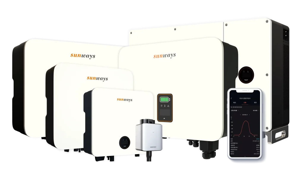
An effective energy management system does more than simply display energy data; it connects photovoltaic generation, energy storage batteries, the grid and loads, and implements appropriate operating strategies based on equipment status, tariff structures and user objectives. An EMS can help you achieve clearer energy management, more efficient battery utilisation, lower O&M costs and more stable system operation.
Sunways combines PV inverters and energy storage solutions with Sunways Cloud to provide unified monitoring and management capabilities for residential, commercial and industrial, and multi-site projects. Through equipment status monitoring, historical data analysis, alarm management, remote O&M and centralised project management, users can gain a more efficient understanding of system performance and establish a reliable data foundation for future energy optimisation.
Start Your Project