Low Voltage Hybrid Inverter: When Does It Make Sense?
Table of Contents
If you are selecting a low-voltage hybrid inverter, focus first on the battery and your actual power requirements. Whether a low-voltage battery solution is suitable depends on whether it can support the discharge power you require, whether it is convenient to lay DC cabling on-site, and how you plan to expand capacity in the future. If you look only at the inverter’s rated power, it is easy to overlook the component that truly limits the system’s performance.
If you are new to energy storage, you might want to read on with one question in mind: Will this combination of battery, inverter and installation solution be able to fulfil my backup power requirements? I will explain this in the following order.
What Does Low Voltage Describe in This System?
In the product classification of hybrid inverters, ‘low voltage’ typically refers to the battery-side DC voltage platform. Direct current (DC) is the form of electrical energy used during battery charging and discharging; domestic appliances generally use alternating current (AC). Hybrid inverters convert and manage electrical energy between different ports, so you need to consider the requirements for the battery, PV input and AC output separately.

To take a practical example: the Sunways STH-5KTL-LS has a battery voltage range of 40–60 V, where ‘V’ stands for volts, the unit of voltage; the AC rated output voltage is listed as 220/230 V, L/N/PE. Here, L, N and PE represent the phase, neutral and protective earth, respectively. This indicates that a low-voltage battery system and domestic AC output can co-exist within the same unit.
Similarly, the Sunways STH-5KTL-LT, which also utilises a 40–60 V battery platform, has an AC rated output listed as 380/400 V, 3L/N/PE, corresponding to a three-phase connection. The battery voltage platform and the number of phases in the AC supply are two distinct selection criteria. When comparing products in practice, first circle the Battery Voltage Range and the AC output/grid type separately in the specification sheet, then check the on-site power supply. This will prevent you from confusing ‘low-voltage batteries’, ‘low-voltage AC distribution’ and ‘single-phase’ as being one and the same thing.
How Does Battery Architecture Affect System Design?
Battery architecture refers to how battery modules are configured and how they exchange electrical energy and operational data with the inverter. A parallel configuration, where permitted by the manufacturer, typically increases energy storage capacity whilst maintaining the same voltage level; a series configuration, as designed by the manufacturer, can increase the battery pack voltage. However, whether a battery is permitted to be configured in this way must be determined by consulting its system design and installation documentation; low-voltage batteries must not be connected in series to form a high-voltage system without authorisation.

You will also encounter the BMS (Battery Management System). This is responsible for monitoring the battery’s status and managing charging, discharging and protection functions in accordance with the battery’s specific conditions. For lithium-ion systems requiring closed-loop communication, the inverter must also correctly receive information regarding the battery’s permissible current, state of charge and alarm signals; the state of charge refers to the proportion of the battery’s remaining capacity. The fact that batteries share the same nominal voltage or form factor does not guarantee that this information can be exchanged correctly.
For example, if you plan to install a set of batteries initially and add modules later, you should confirm with the battery supplier now: whether modules can be added in phases within the same system, and what conditions must be met regarding the model, firmware and operational status of the new modules in relation to the existing ones. Firmware refers to the control software running internally within the equipment. First, draw a schematic diagram of the battery connections for both the current configuration and the expanded configuration, then verify these against the officially permitted configurations. The wiring configuration after parallel connection will also affect the current distribution across each branch and must be verified as part of the system design.
Which Current and Cable Constraints Need Checking?
① Read the Current Limit Alongside the Power Rating
Current is the most commonly overlooked factor in low-voltage systems. For the same DC power, the lower the voltage, the greater the current required. This can be understood using a simple equation: Power P = Voltage V × Current I. Power is usually expressed in watts (W) or kilowatts (kW), where 1 kW = 1,000 W; the unit of current is the ampere (A). The power referred to here is the DC-side power currently under discussion; if you are working backwards from an AC load to determine battery requirements, you must also factor in the inverter’s conversion losses.
The specifications for the Sunways STH-5KTL-LS list the following: rated output power 5,000 W, battery voltage range 40–60 V, and maximum charging/ discharge current of 120/120 A. When these conditions are considered together, it becomes clear why the ‘rated 5 kW’ specification alone cannot fully address all operational issues on the battery side.
For example, if we perform a calculation based solely on voltage and current, 40 V × 120 A = 4,800 W, or 4.8 kW of DC power, without deducting conversion losses. This is an arithmetic derivation based on specification limits; it does not imply that this operating point can be sustained, nor does it represent Sunways’ actual test results or a complete output curve. What it illustrates is that, at lower battery voltages, the current limit may become the first constraint; you must also verify the permissible current ratings of the battery and the BMS, as well as the manufacturer’s specifications for specific operating conditions.
② Check the Whole DC Circuit
Battery current must pass through cables, connection terminals, switches and protective devices, and each component must be appropriately matched. Cables have resistance; when current flows through them, this causes voltage drops and heat generation. A voltage drop is the difference in voltage between the two ends of a circuit during the transmission of electrical energy. Longer cable runs or poor contact at joints can exacerbate these issues.
You may ask the installer to provide a brief DC circuit verification record, which should at least include the following details:
- Design current: Specify the battery voltage, charge and discharge requirements, and equipment limitations used, rather than simply copying the inverter’s kW rating.
- Actual route: Describe the path of the circuit from the battery to the inverter, and how the positive and negative circuits, as well as intermediate connection points, are factored into the calculations.
- Cable conditions: Have the conductor cross-sectional area, installation method, ambient temperature and cable bundling been verified? The conductor cross-sectional area indicates the size of the actual conductive part; it cannot be judged by how thick the outer insulation appears.
- Connections and protection: Do the terminals, busbars, DC switches and protective devices meet the requirements for the corresponding circuits? A busbar is a conductor component that collects current from multiple branches.
Specific cable and protective device specifications should be determined by the installer based on the relevant model manuals and on-site requirements. The purpose of this record is to enable you to understand ‘why this selection was made’ and to re-verify it should the layout change or capacity be increased.
③ Recheck the Design When the Layout Changes
Suppose the original plan placed the batteries next to the inverter, but they were later moved to a more distant location to free up space. Even if the equipment models remain unchanged, the original cable selection must be recalculated. You should first ask the installer to compare the new path lengths, voltage drops and installation conditions before deciding whether to adjust the cables or rearrange the equipment positions; simply extending the original cables is no substitute for a design verification.
How Do Backup Power and Expansion Plans Affect the Choice?
Separating Power from Runtime
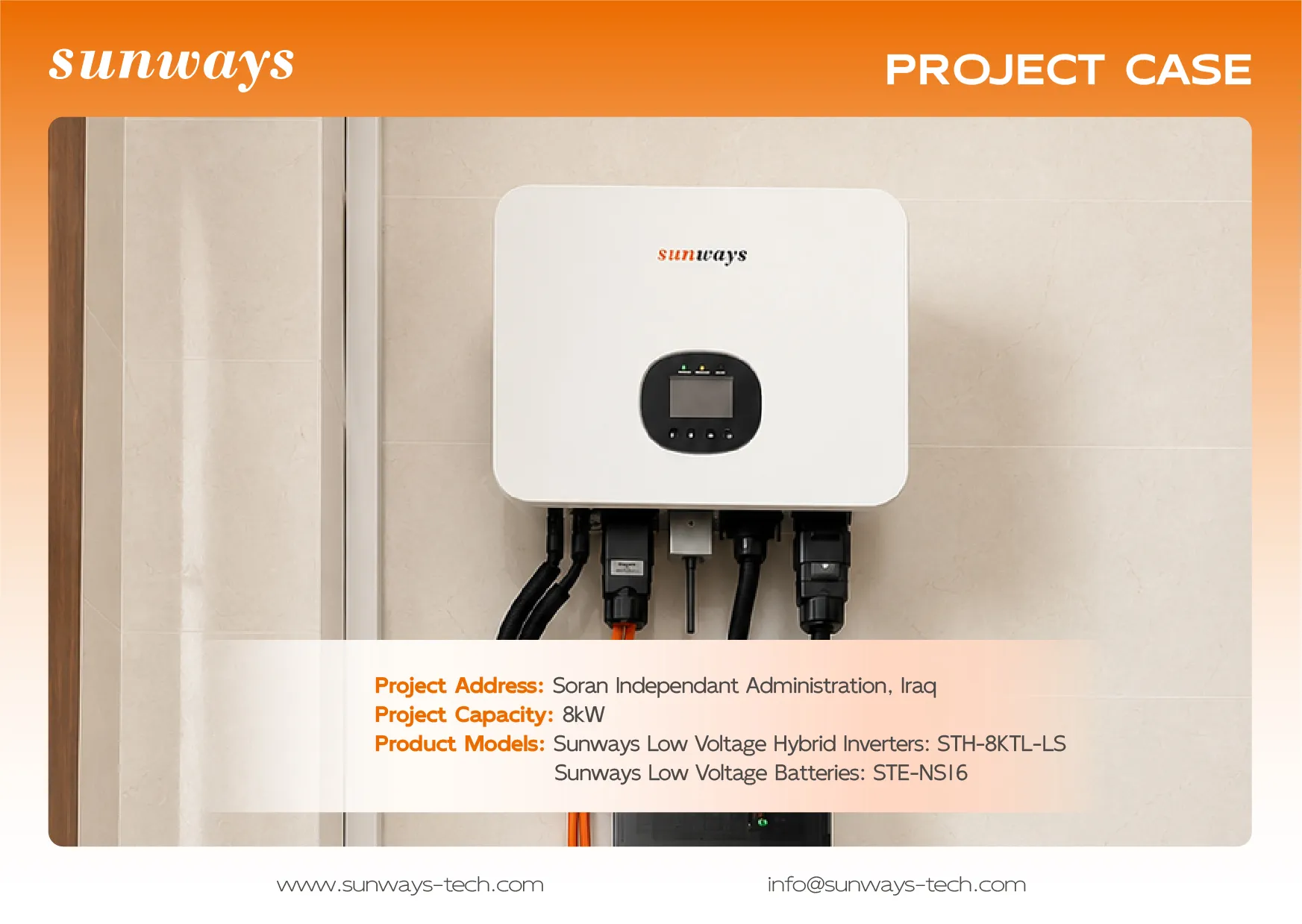
You need to answer two questions simultaneously: which appliances need to run together during a power cut, and how long you want them to run for. kW is power, reflecting how much electricity is required at any given moment; kWh is energy, reflecting how much electricity can be stored or used. Increasing battery storage capacity may help extend runtime, but you will also need to check the limitations of the inverter output, battery discharge power and the backup circuits.
For example, suppose you wish to keep your fridge, lighting and network equipment running during a power cut, and are considering including a water pump in the backup supply. In this case, you should check the daily operating load and the water pump’s start-up requirements separately. Start-up requirements refer to the additional power an appliance may require at the moment it is switched on; whether this can be supported must be assessed by considering the equipment’s continuous output, short-term output and permitted duration, and cannot be inferred simply from the term ‘low voltage’.
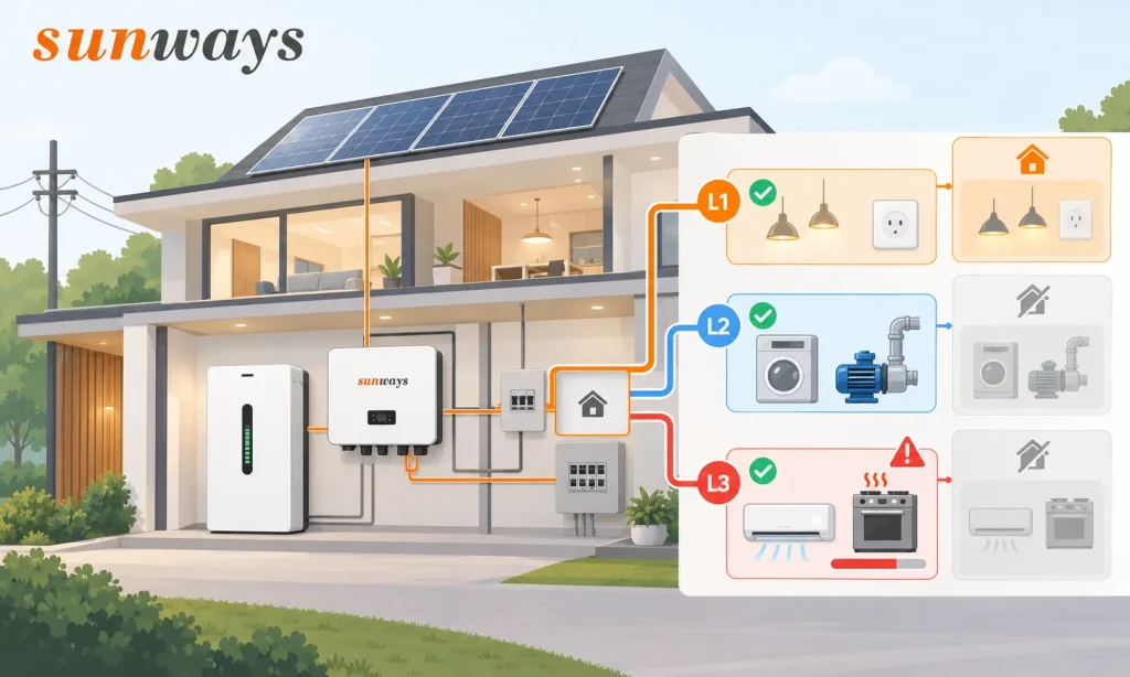
| Your actual objective | Information to be provided to the installer in advance | Key verification points |
|---|---|---|
| Keep essential appliances running for longer | Essential circuits, operating time, usage periods | Currently available battery energy and actual load |
| To run more appliances simultaneously | List of appliances to be run simultaneously and their start-up characteristics | Inverter standby output, permitted battery power and circuit capacity |
| To support three-phase equipment or loads distributed across phases | Number of phases on-site, wiring per phase and load distribution | Total output of the relevant model in standby mode and conditions per phase |
When making a preliminary runtime estimate, the basic relationship can be understood as “available battery energy permitted for discharge × conversion efficiency to the AC side ÷ average standby load”. However, each of these factors must be substantiated, and the average load will also vary with the starting and stopping of appliances. Before purchasing, first compile a list of necessary loads, then ask the supplier to clarify the assumptions regarding electricity consumption, load and losses used to estimate the runtime, to avoid treating the battery’s rated capacity as the final available power.
Treat Expansion as a System Change
Capacity expansion should be divided into two categories: ‘increasing battery energy’ and ‘increasing available power’. The former focuses on the additional modules that can be installed and the battery management conditions; the latter also involves the inverter, power distribution and the DC main circuit. Even if the manufacturer permits battery parallel connection, the actual number of modules that can be added, their configuration and the resulting power output are still constrained by the entire system.
If you are currently providing backup power only for essential circuits but plan to add air conditioning or other significant loads in the future, it is advisable to ask the supplier to outline both the “current configuration” and the “target configuration” within the same proposal. Both configurations should specify the components to be retained, added or replaced, whilst simultaneously verifying the battery parallel connection limits and inverter parallel operation limits; battery parallel connection involves combining battery strings, whilst inverter parallel operation involves multiple inverters operating in concert, and the permissible conditions for the two cannot be interchanged. Differences in the resistance of battery strings must also be factored into the design; it cannot be assumed that, once connected in parallel, each battery group will always bear an equal share of the current.
When Should You Compare a High-Voltage Architecture?

Compare the Constraint You Are Trying to Solve
When backup power requirements increase, DC current demands rise, or the existing layout makes it difficult to arrange cables and connect equipment, it is worth carefully comparing low-voltage vs high-voltage hybrid inverters. Increasing the operating voltage on the battery side can reduce current under the same power conditions; this design flexibility stems from electrical relationships. Whether this ultimately results in a more suitable system still depends on the actual products and on-site conditions.
Taking specific platforms from manufacturers’ documentation as examples: the Sunways STH-5KTL-LS has a battery voltage range of 40–60 V, whilst the STH-5KTL-HS lists a battery voltage range of 85–500 V. These two sets of figures are derived from the battery interface specifications of their respective models and are intended to illustrate the battery platforms employed by different products; they should not be regarded as a uniform low-voltage/high-voltage classification standard applicable to all brands, nor should it be assumed that any battery within the specified range can be connected.
Compare Two Complete Proposals
If the existing low-voltage solution already meets the backup power requirements, installation path constraints and compatibility requirements, you may proceed to evaluate its complete configuration. If the current, cabling or capacity expansion requirements are difficult to meet, ask the supplier to provide a high-voltage proposal as well, and ensure both proposals address the same set of questions.
| Comparison Criteria | Questions for the low-voltage proposal | Questions for the high-voltage proposal |
|---|---|---|
| Can existing batteries be retained? | Have the specific models, condition and communication capabilities been confirmed? | Can the existing batteries be used, or do they need to be replaced with a compatible platform? |
| Is the DC path feasible? | Are the required current, cabling and connecting equipment suitable? | Are the operating voltage, insulation, connection and protection requirements met? |
| Are the backup power requirements the same? | What capacity can be provided for the same load list? | What capacity can be provided for the same load list? |
| Is future capacity expansion clearly defined? | Which modules can be added, and which components need replacing? | How do module combinations, operating voltage ranges and capacity expansion rules change? |
When comparing proposals, you should insist that both proposals use the same backup power objectives, available power capacity and installation scope. Only then can you determine which capabilities or constraints you are prioritising. Battery voltage alone is insufficient to conclude that a particular system is necessarily cheaper, more efficient or easier to expand; if the other party makes such comparisons, you should request the corresponding configurations, quotations or test data to support their claims.
Which Compatibility Documents Are Needed Before Ordering?
Prior to procurement, it is advisable to verify ‘compatibility’ against specific documentation and equipment versions. Taking lithium-ion battery systems as an example, even if both pieces of equipment are labelled CAN or RS485, further verification is still required. These are the names of communication bus/interface categories; to confirm whether the message definitions, wiring and control rules actually in use are compatible, verification at the model and version level is necessary.
You can provide the checklist below directly to the inverter and battery suppliers, requesting that the applicable models, document versions and limitations be included in the project documentation.
| Document or Record | What you need to verify |
|---|---|
| Corresponding model specification sheet | Design limits such as battery voltage, charge and discharge currents, AC and standby outputs |
| Inverter and battery installation manuals | Wiring, protection, installation environment and configuration requirements; confirmation that the manuals correspond to the equipment supplied |
| Current battery compatibility list or written compatibility confirmation | Specified down to battery model, module configuration and applicable inverter, rather than merely brand names |
| Firmware and communication configuration requirements | Internal control software version, protocol selection, cable pinouts and necessary settings |
| Battery Expansion and Parallel Connection Documentation | Permitted combinations, quantities, expansion conditions and battery management requirements |
| Project Configuration and Commissioning Delivery Records | Which equipment and settings were used on-site, and under what conditions were post-installation checks carried out |
For example, if a supplier merely states that ‘this battery supports CAN’, you may request further details regarding the applicable inverter models, minimum firmware requirements and corresponding configuration files. If the parties are unable to confirm the combination at this stage, this should be treated as a procurement condition to be resolved. Sunways’ product documentation download page can serve as a portal for locating the relevant model-specific documents; however, the language, version and market applicability of the documentation must still be confirmed prior to placing an order.
FAQs
Q1. Does low battery voltage imply a low-voltage AC output?
The battery side and the AC side must be checked separately. The battery supplies direct current, which the inverter converts to an AC output according to the specific product design; a ‘low-voltage battery’ does not directly indicate the voltage or number of phases of the AC output. You can refer to the Battery Voltage Range in the specification sheet and compare it with the AC output/grid type; the two Sunways models mentioned in the main text also illustrate this distinction.
Q2. Can batteries with the same nominal voltage use different communication protocols?
Yes. Nominal voltage is an identifier for the battery’s voltage rating and does not indicate which set of communication messages or control rules it uses. Even if the interface names are the same, you should verify the protocol, cable pinout and firmware version, and obtain compatibility documentation applicable to that combination.
Q3. Does battery chemistry alone guarantee inverter compatibility?
No. Battery chemistry describes the technology used in the battery cells—for example, lithium iron phosphate—but a complete battery product also encompasses factors such as battery management, current ratings and communication protocols. When selecting equipment, you must verify the specific combination of battery model and inverter; you cannot base your decision solely on the fact that ‘both are lithium iron phosphate’.
Q4. Can a longer cable route alter the installation design?
Yes. A longer route will affect loop resistance and voltage drop, and actual installation conditions may also change. Whenever the position of the battery or inverter is adjusted, you should have the installer re-verify the cabling, connections and protection design, and update the project records.
Q5. Should parallel battery limits be checked separately from inverter limits?
They should be checked separately. The battery documentation determines which battery combinations are permitted, whilst the inverter documentation determines how the inverter may be connected and operated. Even if both ends permit expansion, the final solution must satisfy communication, electrical connection and control requirements simultaneously; one must not rely solely on the quantity limit at either end.
Q6. Can an existing battery be reused without its model and firmware details?
Without this information, it is impossible to make a reliable assessment of compatibility. You should first collect the nameplate, serial number, firmware information and maintenance records, then ask the supplier to verify suitability and the battery’s condition; do not treat the fact that ‘it worked properly before’ as proof of compatibility with the new system.
Q7. Does a three-phase inverter always require a high-voltage battery?
Not necessarily. The Sunways STH-5KTL-LT, for example, lists both low-voltage battery ranges and three-phase AC output in the same specification sheet. When making a selection, you should verify the battery platform, the number of AC phases and the standby load conditions separately; you cannot directly infer the battery voltage from the fact that it is ‘three-phase’.
Q8. Which supplier should confirm a proposed mixed-brand battery system?
Both the inverter supplier and the battery supplier should separately confirm that their respective equipment supports this combination, and clarify who is responsible for system integration and commissioning. You should obtain documentation that corresponds to specific models, firmware and configurations, to avoid a situation after procurement where both parties merely point the finger at each other regarding compatibility based solely on brand names or interface designations.
Explore Sunways Hybrid Inverters
Explore Sunways hybrid inverters to compare low-voltage options for your battery system, grid connection and backup needs. Before ordering, confirm the exact inverter–battery combination and applicable installation requirements with your supplier.
Start Your Project